
Nissan Versa (N17): Passenger side
PASSENGER SIDE : Exploded View
WITH REMOVABLE HEADREST
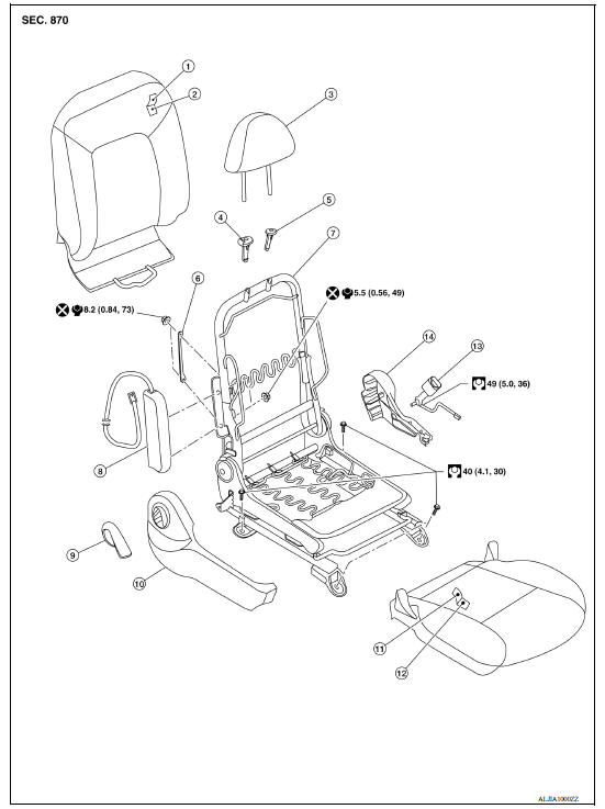
1. Seatback trim 2. Seatback pad 3. Headrest 4. Headrest holder (free) 5. Headrest holder (locked) 6. Chute rod 7. Seat frame assembly 8. Side air bag module 9. Recline lever
WITHOUT REMOVABLE HEADREST
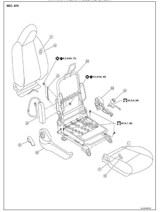
1. Seatback trim 2. Seatback pad 3. Chute rod 4. Side air bag module 5. Recline lever 6. Seat cushion outer finisher (RH) 7. Seat cushion trim 8. Seat cushion pad 9. Seat belt buckle 10. Seat cushion outer finisher (LH) 11. Seat frame assembly
PASSENGER SIDE : Removal and Installation
REMOVAL
WARNING: Do not leave any objects (screwdrivers, tools, etc.) on the seat during seat repair. It can lead to personal injury if the side air bag module should accidentally deploy.
CAUTION:
- When removing or installing the seat trim, handle it carefully to keep dirt out and to avoid damage.
- When checking the power seat circuit for continuity using a circuit tester, do not confuse its connector with the side air bag module connector. Such an error may cause the air bag module to deploy.
- Do not drop, tilt, or bump the side air bag module while installing the seat. Always handle it with care.
- After the front side air bag module inflates, the front seatback assembly must be replaced.
- When removing and installing the seat, use shop cloths to protect components from damage.
- Before removing the front seat, turn the ignition switch OFF, disconnect both battery cables and wait at least three minutes.
- Disconnect the negative and positive battery terminals and wait at least three minutes. Refer to PG "Removal and Installation".
- Slide the seat to the full forward position.
- Remove the two rear seat bolts.
- Slide the seat to the full rearward position.
- Remove the two front seat bolts.
- Tilt the seat rearward to disconnect the harness connectors from the seat and remove.
INSTALLATION
Installation is in the reverse order of removal.
WARNING:
- Perform additional services when installing front passenger seat. Refer to SRC "ZERO POINT RESET : Description".
- Zero point reset must be performed every time the front passenger seat is removed from the vehicle.
- Zero point reset is done after the front passenger seat is installed in vehicle and all bolts are tightened to specification.
CAUTION: Make sure that the seat harness or the floor trim is not damaged during installation.
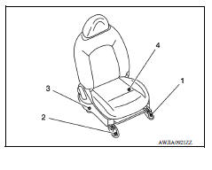
NOTE: When installing the RH front seat, tighten the bolts in the order shown.
RH front seat bolt torque : 40 Nm (4.1 kg-m, 30 ft-lb)
 Front seat
DRIVER SIDE DRIVER SIDE : Exploded View WITH REMOVABLE HEADREST 1. Armrest (if equipped) 2. Seat cushion outer finisher (RH) 3. Seat belt buckle 4. Seat cushion trim 5. Seat cushion pad 6. S ...
Rear seat
Exploded View - Fixed Seatback FIXED SEATBACK 1. Headrest holder (locked) 2. Headrest holder (free) 3. Rear seatback assembly 4. Seatback trim 5. Seatback pad 6. LATCH bracket (RH) 7. Seat c ...
Other materials:
Fuel tank
Exploded View
1. Fuel tank 2. Fuel tank mounting band (RH) 3. Fuel tank mounting band (LH)
4. Clamp 5. Fuel filler hose 6. Fuel filler tube
7. Grommet 8. Fuel filler cap 9. Clamp
10. Vent hose
Removal and Installation
WARNING:
Be sure to read "General Precautions" before working on the fu ...
Gear oil
Inspection
OIL LEAKAGE
Make sure that gear oil is not leaking from transaxle or around it.
OIL LEVEL
Remove filler plug (1) and gasket from transaxle case.
Check the oil level from filler plug hole as shown. CAUTION:
Do not start engine while checking oil level.
Install a new gas ...
Categories
- Manuals Home
- Nissan Versa Owners Manual
- Nissan Versa Service Manual
- Video Guides
- Questions & Answers
- External Resources
- Latest Updates
- Most Popular
- Sitemap
- Search the site
- Privacy Policy
- Contact Us

0.0124