Nissan Versa (N17): Rear seat
Exploded View - Fixed Seatback
FIXED SEATBACK
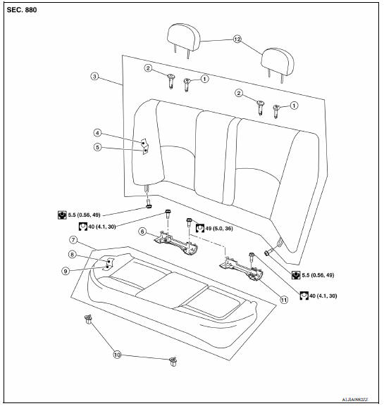
1. Headrest holder (locked) 2. Headrest holder (free) 3. Rear seatback assembly 4. Seatback trim 5. Seatback pad 6. LATCH bracket (RH) 7. Seat cushion assembly 8. Seat cushion trim 9. Seat cushion pad 10. Seat cushion hook 11. LATCH bracket (LH) 12. Headrest
Exploded View - 60:40 Split Seatback
60:40 SPLIT SEATBACK
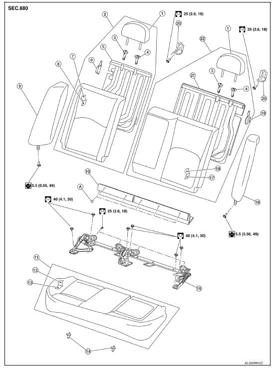
1. Headrest 2. Rear seatback assembly (RH) 3. Headrest holder (free) 4. Headrest holder (locked) 5. Rear seatback frame (RH) 6. Seatback latch assembly (RH) 7. Seatback trim (RH) 8. Seatback pad (RH) 9. Rear seat bolster (RH) 10. Seatback hinge finisher 11. Seat cushion assembly 12. Seat cushion trim 13. Seat cushion pad 14. Seat cushion hook 15. Seatback hinge assembly 16. Rear seat bolster (LH) 17. Seatback pad (LH) 18. Seatback trim (LH) 19. Seatback latch assembly (LH) 20. Seatback striker 21. Rear seatback frame (LH) 22. Rear seatback assembly (LH) A. Seatback hinge finisher clips
Removal and Installation - Seat Cushion Assembly
REMOVAL
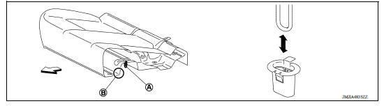
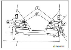
1. Lift up the seat cushion assembly close to the front edge (B) to release it from the seat cushion hooks (A) (one for each side) and remove the seat cushion assembly.
 : Front
INSTALLATION
Installation is in the reverse order of removal.
Removal and Installation - Fixed Seatback
REMOVAL
- Remove the seat cushion assembly. Refer to SE "Removal and Installation - Seat Cushion Assembly".
- Remove the rear seat belt D-ring anchors (LH/RH). Refer to SB "Exploded View".
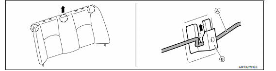
- Remove the two seatback bolts.
- Lift the rear seatback assembly upward and disengage the seatback frame (A) from body hook (B) and remove the rear seatback assembly.
INSTALLATION
Installation is in the reverse order of removal.
- Tighten the rear seatback assembly bolts to specification. Refer to SE "Exploded View - Fixed Seatback".
- Tighten the rear seat belt D-ring anchors to specification. Refer to SB"Exploded View".
Removal and Installation - 60:40 Split Seatback
REMOVAL
- Place the rear seatback assembly in the folded down position.
- Release the hook fasteners (A) in the lower corners of the rear seatback assembly.
- Remove the rear seatback assembly bolts (B) from the seatback hinge assembly (1), then remove the rear seatback assembly.
INSTALLATION
Installation is in the reverse order of removal.
Tighten the rear seatback assembly bolts to specification. Refer to SE "Exploded View - 60:40 Split Seatback".
Removal and Installation - Seatback Hinge Assembly
- Remove the seat cushion assembly. Refer to SE "Removal and Installation - Seat Cushion Assembly".
- Remove the rear seatback assemblies (LH/RH). Refer to SE "Removal and Installation - 60:40 Split Seatback"
- Remove the rear seat bolsters (LH/RH). Refer to SE "Removal and Installation - Rear Seat Bolster"
- Remove the bolts and the seatback hinge assembly.
INSTALLATION
Installation is in the reverse order of removal.
- Tighten the seatback hinge assembly bolts to specification. Refer to SE "Exploded View - 60:40 Split Seatback".
Removal and Installation - Rear Seat Bolster
REMOVAL
- Remove the seat cushion assembly. Refer to SE "Removal and Installation - Seat Cushion Assembly".
- Remove the bolt at bottom of rear seat bolster.
- Lift the rear seat bolster to remove.
INSTALLATION
Installation is in the reverse order of removal.
- Tighten rear seat bolster bolt to specification. Refer to SE "Exploded View - 60:40 Split Seatback".
Removal and Installation - Seat Cushion Hook
REMOVAL
- Remove the seat cushion assembly. Refer to SE "Removal and Installation - Seat Cushion Assembly".
- Release the seat cushion hook pawls as shown and remove.
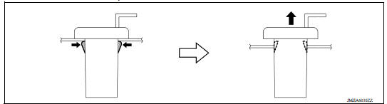
CAUTION: Before removing/installing the seat cushion hook, check its orientation (front/rear).
INSTALLATION
Installation is in the reverse order of removal.
UNIT DISASSEMBLY AND ASSEMBLY
 Passenger side
PASSENGER SIDE : Exploded View WITH REMOVABLE HEADREST 1. Seatback trim 2. Seatback pad 3. Headrest 4. Headrest holder (free) 5. Headrest holder (locked) 6. Chute rod 7. Seat frame assembly 8. ...
Front seat
DRIVER SIDE DRIVER SIDE : Exploded View WITH REMOVABLE HEADREST 1. Armrest (if equipped) 2. Seat cushion outer finisher (RH) 3. Seat belt buckle 4. Seat cushion trim 5. Seat cushion pad 6. ...
Other materials:
NISSAN Voice Recognition System (if so equipped)
The NISSAN Voice Recognition system allows
hands-free operation of the systems equipped on
this vehicle, such as the phone and navigation
systems.
To operate NISSAN Voice Recognition, press
the button located on the steering
wheel.
When prompted, speak the command for the
system you wi ...
Emission control system warranty
Your NISSAN vehicle is covered by the following
emission warranties:
For USA
1. Emission Defects Warranty
2. Emissions Performance Warranty
Details of this warranty may be found with other
vehicle warranties in your Warranty Information
Booklet which comes with your NISSAN vehicle.
If you ...
Categories
- Manuals Home
- Nissan Versa Owners Manual
- Nissan Versa Service Manual
- Video Guides
- Questions & Answers
- External Resources
- Latest Updates
- Most Popular
- Sitemap
- Search the site
- Privacy Policy
- Contact Us

0.0052