Nissan Versa (N17): Cooling fan control
Cooling fan control : system diagram
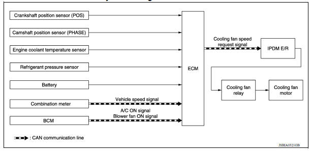
Cooling fan control : system description
INPUT/OUTPUT SIGNAL CHART
| Sensor | Input signal to ECM | ECM function | Actuator |
| Crankshaft position sensor (POS) Camshaft position sensor (PHASE) | Engine speed*1 Piston position | Cooling fan speed request signal | IPDM E/R ↓ Cooling fan relay ↓ Cooling fan motor |
| Engine coolant temperature sensor | Engine coolant temperature | ||
| Battery | Battery voltage*1 | ||
| Refrigerant pressure sensor | Refrigerant pressure | ||
| Combination meter | Vehicle speed signal*2 | ||
| BCM | A/C ON signal*2 Blower fan signal*2 |
*1: The ECM determines the start signal status by the signals of engine speed and battery voltage.
*2: This signal is sent to ECM through CAN communication line.
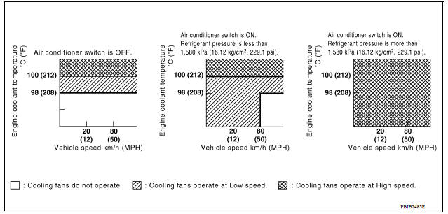
SYSTEM DESCRIPTION (EXCEPT FOR SINGLE CONNECTOR COOLING FAN WITHOUT A/C)
ECM controls cooling fan speed corresponding to vehicle speed, engine coolant temperature, refrigerant pressure, air conditioner ON signal. Then control system has 3step control [HIGH/LOW/OFF].
Cooling Fan Operation
Cooling Fan Relay Operation
The ECM controls cooling fan relays through CAN communication line.
| Cooling fan speed | Cooling fan low relay | Cooling fan high relay | Cooling fan relay |
| Stop (OFF) | OFF | OFF | OFF |
| Low (LOW) | ON | OFF | OFF |
| High (HI) | ON | ON | ON |
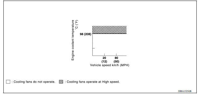
SYSTEM DESCRIPTION (FOR SINGLE CONNECTOR COOLING FAN WITHOUT A/C)
ECM controls cooling fan speed corresponding to vehicle speed, engine coolant temperature, refrigerant pressure, air conditioner ON signal. Then control system has 2step control [HIGH/OFF].
Cooling Fan Operation
Cooling Fan Relay Operation
The ECM controls cooling fan relays through CAN communication line.
| Cooling fan speed | Cooling fan low relay |
| Stop (OFF) | OFF |
| Operate (HI) | ON |
 Air conditioning cut control
AIR CONDITIONING CUT CONTROL : System Diagram AIR CONDITIONING CUT CONTROL : System Description INPUT/OUTPUT SIGNAL CHART Sensor Input signal to ECM ECM function Actuator ...
Evaporative emission system
EVAPORATIVE EMISSION SYSTEM : System Diagram EVAPORATIVE EMISSION SYSTEM : System Description INPUT/OUTPUT SIGNAL CHART Sensor Input signal to ECM ECM function Actuator ...
Other materials:
Input shaft and gear
Exploded View
1. Input shaft front bearing 2. Input shaft 3. Snap ring
4. Input shaft rear bearing 5. Adapter plate 6. Bushing
7. 5th input gear 8. 5th-reverse baulk ring 9. Synchronizer lever
10. 5th-reverse synchronizer hub 11. 5th-reverse coupling sleeve 12. Lock washer
13. Retaining pi ...
Id registration procedure
Description
This procedure must be performed after replacing wheels, transmitters or the
BCM, or rotating wheels.
Work Procedure
NOTE:
The Signal Tech II Tool (J-50190) can be used to perform the following
functions. Refer to the Signal Tech II
User Guide for additional information.
Ac ...
Categories
- Manuals Home
- Nissan Versa Owners Manual
- Nissan Versa Service Manual
- Video Guides
- Questions & Answers
- External Resources
- Latest Updates
- Most Popular
- Sitemap
- Search the site
- Privacy Policy
- Contact Us

0.0049