Nissan Versa (N17): Evaporative emission system
EVAPORATIVE EMISSION SYSTEM : System Diagram
EVAPORATIVE EMISSION SYSTEM : System Description
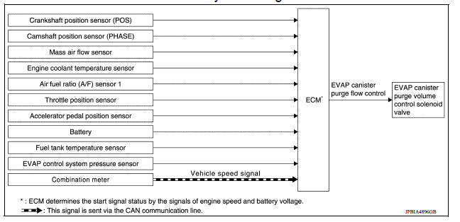
INPUT/OUTPUT SIGNAL CHART
| Sensor | Input signal to ECM | ECM function | Actuator |
| Crankshaft position sensor (POS) Camshaft position sensor (PHASE) | Engine speed*1 Piston position | EVAP canister purge flow control | EVAP canister purge volume control solenoid valve |
| Mass air flow sensor | Amount of intake air | ||
| Engine coolant temperature sensor | Engine coolant temperature | ||
| Air fuel ratio (A/F) sensor 1 | Density of oxygen in exhaust gas (Mixture ratio feedback signal) | ||
| Throttle position sensor | Throttle position | ||
| Accelerator pedal position sensor | Accelerator pedal position | ||
| Battery | Battery voltage*1 | ||
| Fuel tank temperature sensor | Fuel temperature in fuel tank | ||
| EVAP control system pressure sensor | Pressure in purge line | ||
| Combination meter | Vehicle speed*2 |
*1: ECM determines the start signal status by the signals of engine speed and battery voltage.
*2: This signal is sent to the ECM through CAN communication line.
SYSTEM DESCRIPTION
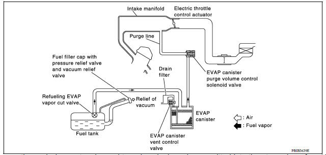
The evaporative emission system is used to reduce hydrocarbons emitted into the atmosphere from the fuel system. This reduction of hydrocarbons is accomplished by activated charcoals in the EVAP canister.
The fuel vapor in the sealed fuel tank is led into the EVAP canister which contains activated carbon and the vapor is stored there when the engine is not operating or when refueling to the fuel tank.
The vapor in the EVAP canister is purged by the air through the purge line to the intake manifold when the engine is operating. EVAP canister purge volume control solenoid valve is controlled by ECM. When the engine operates, the flow rate of vapor controlled by EVAP canister purge volume control solenoid valve is proportionally regulated as the air flow increases.
EVAP canister purge volume control solenoid valve also shuts off the vapor purge line during decelerating.
 Cooling fan control
Cooling fan control : system diagram Cooling fan control : system description INPUT/OUTPUT SIGNAL CHART Sensor Input signal to ECM ECM function Actuator Crankshaft po ...
Intake valve timing control
Intake valve timing control : System Diagram Intake valve timing control : system description INPUT/OUTPUT SIGNAL CHART Sensor Input signal to ECM ECM function Actuator ...
Other materials:
Power outlets
Instrument panel
Console (if so equipped)
The power outlets are for powering electrical
accessories such as cellular telephones. The
outlets are rated at 12 volt, 120W (10A) maximum.
CAUTION
The outlet and plug may be hot during
or immediately after use.
Only certain power outlets ...
Service data and specifications
(SDS)
Periodical Maintenance Specification
ENGINE OIL CAPACITY (APPROXIMATE)
...
Categories
- Manuals Home
- Nissan Versa Owners Manual
- Nissan Versa Service Manual
- Video Guides
- Questions & Answers
- External Resources
- Latest Updates
- Most Popular
- Sitemap
- Search the site
- Privacy Policy
- Contact Us

0.0057