Nissan Versa (N17): Air conditioning cut control
AIR CONDITIONING CUT CONTROL : System Diagram
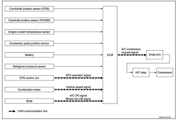
AIR CONDITIONING CUT CONTROL : System Description
INPUT/OUTPUT SIGNAL CHART
| Sensor | Input signal to ECM | ECM function | Actuator |
| Crankshaft position sensor (POS) Camshaft position sensor (PHASE) | Engine speed*1 Piston position | A/C compressor request signal | IPDM E/R ↓ Air conditioner relay ↓ Compressor |
| Engine coolant temperature sensor | Engine coolant temperature | ||
| Accelerator pedal position sensor | Accelerator pedal position | ||
| Battery | Battery voltage*1 | ||
| Refrigerant pressure sensor | Refrigerant pressure | ||
| EPS control unit | EPS operation signal*2 | ||
| Combination meter | Vehicle speed signal*2 | ||
| BCM | A/C ON signal*2 Blower fan signal*2 |
*1: ECM determines the start signal status by the signals of engine speed and battery voltage.
*2: This signal is sent to the ECM through CAN communication line.
SYSTEM DESCRIPTION
This system improves engine operation when the air conditioner is used.
Under the following conditions, the air conditioner is turned off.
- When the accelerator pedal is fully depressed.
- When cranking the engine.
- At high engine speeds.
- When the engine coolant temperature becomes excessively high.
- When operating power steering during low engine speed or low vehicle speed.
- When engine speed is excessively low.
- When refrigerant pressure is excessively low or high.
Can communication
CAN COMMUNICATION : System Description
CAN (Controller Area Network) is a serial communication line for real time application. It is an onvehicle multiplex communication line with high data communication speed and excellent error detection ability. Many electronic control units are equipped onto a vehicle, and each control unit shares information and links with other control units during operation (not independent). In CAN communication, control units are connected with 2 communication lines (CAN H line, CAN L line) allowing a high rate of information transmission with less wiring.
Each control unit transmits/receives data but selectively reads required data only.
 Electric ignition system
ELECTRIC IGNITION SYSTEM : System Diagram ELECTRIC IGNITION SYSTEM : System Description INPUT/OUTPUT SIGNAL CHART Sensor Input signal to ECM ECM function Actuator Cran ...
Cooling fan control
Cooling fan control : system diagram Cooling fan control : system description INPUT/OUTPUT SIGNAL CHART Sensor Input signal to ECM ECM function Actuator Crankshaft po ...
Other materials:
Recommended fluids/lubricants and capacities
The following are approximate capacities. The actual refill capacities may
be a little different. When refilling, follow the procedure
described in the "Do-it-yourself" section to determine the proper refill
capacity.
...
Additional service when replacing
TCM
Description
Always perform the following items when the TCM is replaced.
LOADING OF THE CALIBRATION DATA
The TCM acquires calibration data (individual characteristic value) of
each solenoid that is stored in the
ROM assembly (in the control valve). This enables the TCM to perform
accur ...
Categories
- Manuals Home
- Nissan Versa Owners Manual
- Nissan Versa Service Manual
- Video Guides
- Questions & Answers
- External Resources
- Latest Updates
- Most Popular
- Sitemap
- Search the site
- Privacy Policy
- Contact Us

0.0047