Nissan Versa (N17): Diagnosis and repair work flow
Work Flow
OVERALL SEQUENCE
DETAILED FLOW
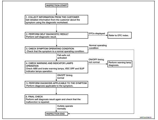
1.COLLECT INFORMATION FROM THE CUSTOMER
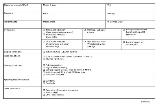
Get detailed information from the customer about the symptom (the condition and the environment when the incident/malfunction occurred) using the diagnostic worksheet. Refer to BRC "Diagnostic Work Sheet".
>> GO TO 2.
2.PERFORM SELF DIAGNOSTIC RESULT
Perform self diagnostic result. Refer to BRC "CONSULT Function (ABS)".
Are any DTCs displayed?
YES >> Refer to BRC "DTC Index".
NO >> GO TO 3.
3.CHECK SYMPTOM OPERATING CONDITION
Check that the symptom is a normal operating condition. Refer to BRC "Description".
Is the symptom a normal operating condition?
YES >> Inspection End.
NO >> GO TO 4.
4.CHECK WARNING AND INDICATOR LAMPS OPERATION
Check ABS and brake warning lamps, and VDC OFF and SLIP indicator lamps operation. Refer to MWI "METER SYSTEM : System Description" (type A) or MWI "METER SYSTEM : System Description" (type B).
Is ON/OFF timing normal?
YES >> GO TO 5.
NO >> Perform warning lamp diagnosis. Refer to BRC "Component Function Check" (ABS warning lamp), BRC "Component Function Check" (brake warning lamp), BRC "Component Function Check" (VDC OFF indicator lamp) or BRC "Component Function Check" (SLIP indicator lamp).
5.PERFORM DIAGNOSIS APPLICABLE TO THE SYMPTOM
Perform diagnosis applicable to the symptom. Refer to BRC "Symptom Table".
>> GO TO 6.
6.FINAL CHECK
Perform self diagnostic result again, and check that the malfunction is repaired. After checking, erase the self diagnosis memory. Refer to BRC "CONSULT Function (ABS)".
>> Inspection End.
Diagnostic Work Sheet
ADDITIONAL SERVICE WHEN REPLACING ABS ACTUATOR AND ELECTRIC UNIT (CONTROL UNIT)
Description
After replacing the ABS actuator and electric unit (control unit), perform the neutral position adjustment for the steering angle sensor. Refer to BRC "Work Procedure".
Work Procedure
1.PERFORM THE NEUTRAL POSITION ADJUSTMENT FOR THE STEERING ANGLE SENSOR
Perform the neutral position adjustment for the steering angle sensor.
>> Refer to BRC "Work Procedure".
 ABS Actuator and electric unit
(control unit)
ABS Actuator and electric unit
(control unit)Adjustment of steering angle sensor
neutral position
Description Refer to the table below to determine if adjustment of steering angle sensor neutral position is required. Work Procedure ADJUSTMENT OF STEERING ANGLE SENSOR NEUTRAL POSITION C ...
Other materials:
U0073 Communication bus a off
DTC Logic
DTC
Trouble diagnosis name
DTC detecting condition
Possible causes
U0073
Control Module Communication
Bus "A" Off
When the ignition switch is ON,
TCM detects a bus-off error
continuously for 2 seconds or
more.
Harness or connector
(CA ...
P0705 Transmission range switch A
DTC Logic
DTC DETECTION LOGIC
DTC
Trouble diagnosis name
DTC detection condition
Possible causes
P0705
Transmission Range Sensor
"A" Circuit Malfunction (PRNDL
input)
The following diagnosis conditions
are met and 2 or more position
signals are ON at the
...
Categories
- Manuals Home
- Nissan Versa Owners Manual
- Nissan Versa Service Manual
- Video Guides
- Questions & Answers
- External Resources
- Latest Updates
- Most Popular
- Sitemap
- Search the site
- Privacy Policy
- Contact Us

0.0055