Nissan Versa (N17): Component parts
POWER DOOR LOCK SYSTEM
POWER DOOR LOCK SYSTEM : Component Parts Location
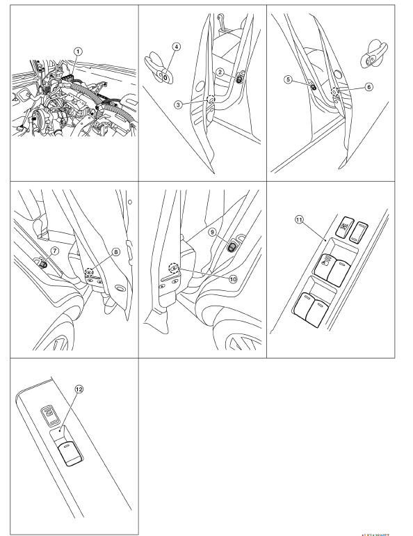
1. BCM (shown with instrument panel removed) 2. Front door switch LH 3. Front door lock actuator LH 4. Front door lock key cylinder switch LH 5. Front door switch RH 6. Front door lock actuator RH 7. Rear door switch RH 8. Rear door lock actuator RH 9. Rear door lock switch LH 10. Rear door lock actuator LH 11. Main power window and door lock/ unlock switch 12. Power window and door lock/unlock switch RH
POWER DOOR LOCK SYSTEM :
Component Description
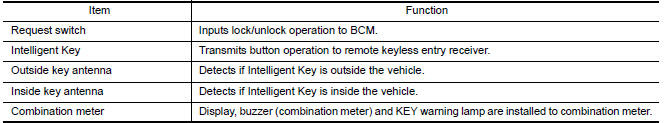
INTELLIGENT KEY SYSTEM
INTELLIGENT KEY SYSTEM : Component Parts Location
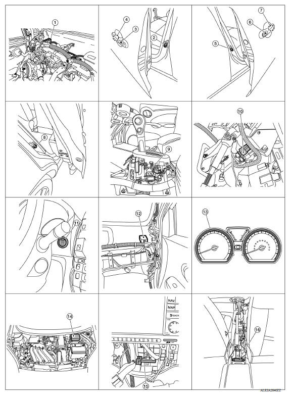
1. BCM (view with instrument panel removed) 2. Front door switch LH 3. Door request switch LH 4. Outside key antenna LH 5. Front door switch RH 6. Door request switch RH 7. Outside key antenna RH 8. Rear door switch RH (rear door switch LH similar) 9. CVT shift selector (park position switch) (view with center console removed) 10. Brake switch 11. Push-button ignition switch 12. Remote keyless entry receiver (view with instrument panel removed) 13. Combination meter (type B) 14. IPDM E/R 15. Inside key antenna (center) 16. Inside key antenna (console) (view with center console removed) 17. Inside key antenna (trunk room) 18. Trunk room lamp switch 19. Outside key antenna (rear bumper) (view with rear bumper facia removed) 20. Horn relay (shown with IPDM E/R removed) 21. Horn
INTELLIGENT KEY SYSTEM :
Component Description 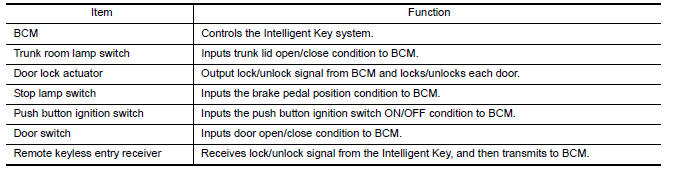
TRUNK LID OPENER SYSTEM
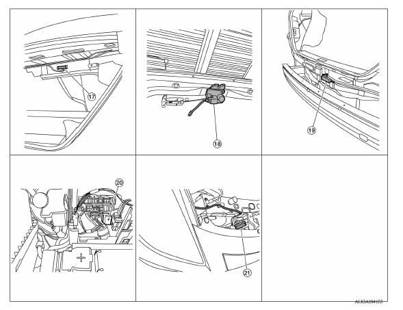
TRUNK LID OPENER SYSTEM : Component Parts Location
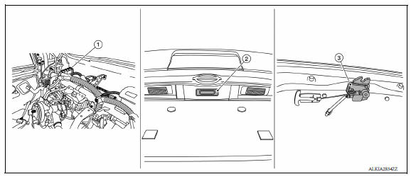
1. BCM (view with instrument panel removed) 2. Trunk lid switch 3. Trunk lid lock assembly (trunk lid opener actuator and trunk lid switch)
TRUNK LID OPENER SYSTEM :
Component Description 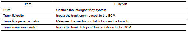
 Precautions
System (power door lock system)
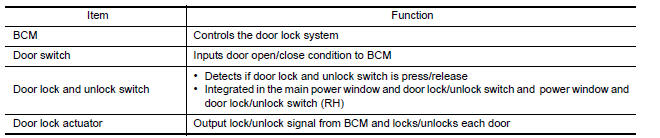
System Diagram System Description DOOR LOCK FUNCTION The door lock and unlock switch (driver side) is built into power window main switch. The door lock and unlock switch (pa ...
Other materials:
Increasing fuel economy
Keep your engine tuned up.
Follow the recommended scheduled maintenance.
Keep the tires inflated to the correct pressure.
Low tire pressure increases tire wear
and lowers fuel economy.
Keep the wheels in correct alignment. Improper
alignment increases tire wear and
lowers fuel eco ...
Precautions
Precaution for Supplemental Restraint System
(SRS) "AIR BAG" and "SEAT BELT PRE-TENSIONER"
The Supplemental Restraint System such as "AIR BAG" and "SEAT BELT
PRE-TENSIONER", used along
with a front seat belt, helps to reduce the risk or severity of injury to the
driver and ...
Categories
- Manuals Home
- Nissan Versa Owners Manual
- Nissan Versa Service Manual
- Video Guides
- Questions & Answers
- External Resources
- Latest Updates
- Most Popular
- Sitemap
- Search the site
- Privacy Policy
- Contact Us

0.0074