Nissan Versa (N17): Component parts
AUTOMATIC DOOR LOCK/UNLOCK FUNCTION
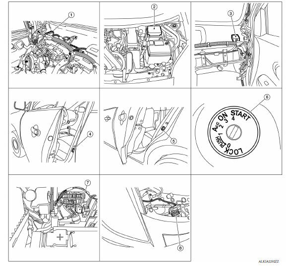
AUTOMATIC DOOR LOCK/UNLOCK FUNCTION : Component Parts Location
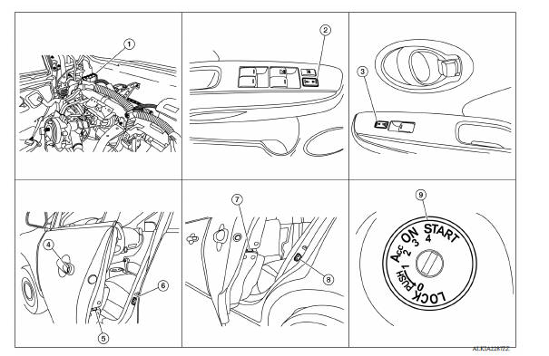
1. BCM (view with instrument panel removed) 2. Main power window and door lock/unlock switch 3. Power window and door lock/unlock switch RH 4. Front door lock key cylinder switch LH 5. Front door lock actuator LH (RH similar) 6. Front door switch LH (RH similar) 7. Rear door lock actuator LH (RH similar) 8. Rear door switch LH (RH similar) 9. Key switch
AUTOMATIC DOOR LOCK/UNLOCK FUNCTION
: Component Description 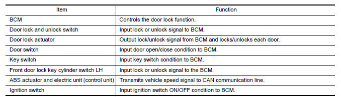
POWER DOOR LOCK SYSTEM
POWER DOOR LOCK SYSTEM : Component Parts Location
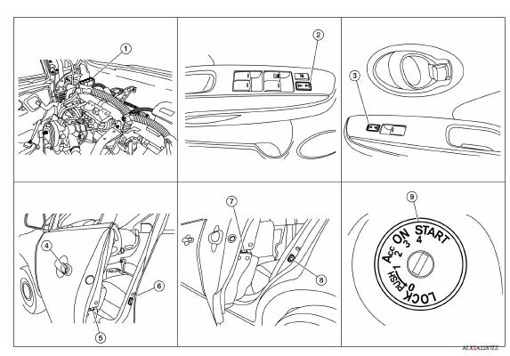
1. BCM (view with instrument panel removed) 2. Main power window and door lock/unlock switch 3. Power window and door lock/unlock switch RH 4. Front door lock key cylinder switch LH 5. Front door lock actuator LH (RH similar) 6. Front door switch LH (RH similar) 7. Rear door lock actuator LH (RH similar) 8. Rear door switch LH (RH similar) 9. Key switch
POWER DOOR LOCK SYSTEM :
Component Description 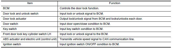
REMOTE KEYLESS ENTRY SYSTEM
REMOTE KEYLESS ENTRY SYSTEM : Component Parts Location
1. BCM (view with instrument panel removed) 2. IPDM E/R 3. Remote keyless entry receiver (view with instrument panel removed) 4. Front door switch LH (RH similar) 5. Rear door switch LH (RH similar) 6. Key switch 7. Horn relay (view with IPDM E/R removed) 8. Horn
REMOTE KEYLESS ENTRY SYSTEM :
Component Description 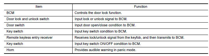
TRUNK LID OPENER SYSTEM
TRUNK LID OPENER SYSTEM : Component Parts Location
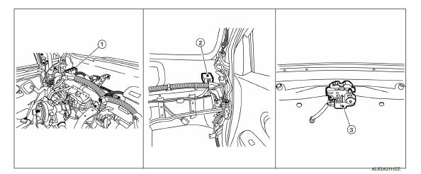
1. BCM (view with instrument panel removed) 2. Remote keyless entry receiver (view with instrument panel removed) 3. Trunk lid opener actuator
TRUNK LID OPENER SYSTEM : Component Description 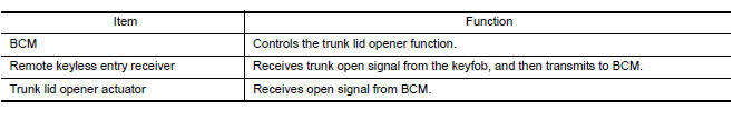
SYSTEM
 Precautions
Automatic door lock/unlock function
AUTOMATIC DOOR LOCK/UNLOCK FUNCTION : System Diagram AUTOMATIC DOOR LOCK/UNLOCK FUNCTION : System Description DOOR LOCK FUNCTION The door lock and unlock switch (driver side) is built i ...
Other materials:
Fuel pressure check
Work Procedure
FUEL PRESSURE RELEASE
1.FUEL PRESSURE RELEASE
With CONSULT
Turn ignition switch ON.
Perform "FUEL PRESSURE RELEASE" in "WORK SUPPORT" mode with CONSULT.
Start engine.
After engine stalls, crank it two or three times to release all fuel
pressure.
Turn ignition switc ...
Control cable
Exploded View
1. Bracket B 2. Lock plate 3. Transaxle assembly
4. Bracket A 5. Control cable 6. Shift selector assembly
A: Manual lever B: Grommet
Removal and Installation
CAUTION:
Always apply the parking brake before performing removal and installation.
REMOVAL
Remove the battery. R ...
Categories
- Manuals Home
- Nissan Versa Owners Manual
- Nissan Versa Service Manual
- Video Guides
- Questions & Answers
- External Resources
- Latest Updates
- Most Popular
- Sitemap
- Search the site
- Privacy Policy
- Contact Us

0.0058