Nissan Versa (N17): Control cable
Exploded View
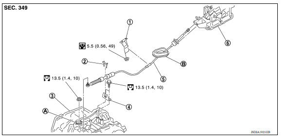
1. Bracket B 2. Lock plate 3. Transaxle assembly 4. Bracket A 5. Control cable 6. Shift selector assembly A: Manual lever B: Grommet
Removal and Installation
CAUTION: Always apply the parking brake before performing removal and installation.
REMOVAL
- Remove the battery. Refer to PG "Removal and Installation".
- Remove the TCM and bracket. Refer to TM "Removal and Installation".
- Remove the IPDM E/R. Refer to PCS "Removal and Installation".
- Remove the center console. Refer to IP "Removal and Installation".
- Remove the control cable from the shift selector assembly.
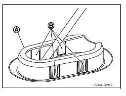
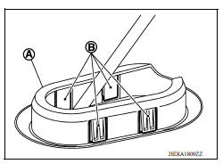
- Disengage the pawls (B) of the grommet (A), and pull downwards to remove.
- Remove the control cable nut from the manual lever.
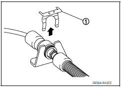
8. Remove the lock plate (1).
9. Lift up the heat plate.
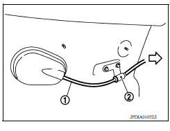
10. Remove the control cable (1) from the bracket (2).
 : Front
11. Remove the control cable from the vehicle.
12. Remove bracket.
INSTALLATION
Installation is in the reverse order of removal.
- From below the vehicle, press the grommet (A) into place until the
pawls (B) make a click sound.
CAUTION: Check that pulling down on the grommet does not disconnect it.
- Pay attention to the following when connecting the control cable to the shift selector.
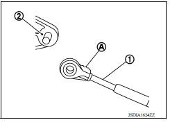
1. When connecting the control cable (1) to the shift selector assembly (2), face the grooved surface of the rib (A) up and insert the control cable until it stops.
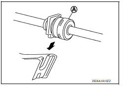
2. Install the socket (A) onto the shift selector assembly.
CAUTION:
- Insert the socket into the shift selector assembly, then push it firmly in place.
- Check that pulling on the socket does not disconnect it.
Inspection
INSPECTION AFTER INSTALLATION
Check the A/T position. If a malfunction is found, adjust the A/T position. Refer to TM "Inspection and Adjustment".
 A/T Shift selector
Exploded View 1. Shift selector handle 2. Lock pin 3. Shift selector handle cover 4. Position indication panel 5. Shift selector assembly ...
Key interlock cable
Exploded View 1. A/T shift selector assembly 2. Key interlock cable A: Key cylinder B: Lock plate C: Clip Removal and Installation CAUTION: Always apply the parking brake before performin ...
Other materials:
Drive belt
1. Water pump pulley
2. Generator pulley
3. Manual tensioner pulley
4. Air conditioner compressor pulley
5. Crankshaft pulley
WARNING
Be sure the ignition switch is placed in the
OFF or LOCK position before servicing
drive belt. The engine could rotate
unexpectedly.
1. Visually inspect t ...
Vacuum lines
Exploded View
1. Clamp 2. Vacuum hose 3. Vacuum piping
A. To brake booster B. Paint mark C. To intake manifold
Removal and Installation
REMOVAL
Remove the air cleaner and duct assembly. Refer to EM "Exploded View".
Remove the vacuum hose and vacuum piping.
INSTALLATION
...
Categories
- Manuals Home
- Nissan Versa Owners Manual
- Nissan Versa Service Manual
- Video Guides
- Questions & Answers
- External Resources
- Latest Updates
- Most Popular
- Sitemap
- Search the site
- Privacy Policy
- Contact Us

0.0054