Nissan Versa (N17): Structure and operation
Sectional View
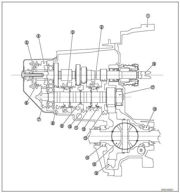
1. Clutch housing 2. 1st-2nd synchronizer hub assembly 3. 3rd-4th synchronizer hub assembly 4. 5th input gear 5. 5th-reverse synchronizer hub assembly 6. 5th-reverse baulk ring 7. 5th main gear 8. 4th main gear 9. 3rd main gear 10. 2nd main gear 11. 2nd double-cone synchronizer 12. 1st double-cone synchronizer 13. 1st main gear 14. Differential side bearing 15. Differential 16. Final gear 17. Mainshaft 18. Input shaft
System Description
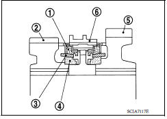
DOUBLE-CONE SYNCHRONIZER
Double-cone synchronizers are adopted for 1st and 2nd gears to reduce operating force of the shift selector.
(1) : Outer baulk ring
(2) : 2nd main gear
(3) : Synchronizer cone
(4) : Inner baulk ring
(5) : 1st main gear
(6) : 1st-2nd coupling sleeve
REVERSE GEAR NOISE PREVENTION FUNCTION (REVERSE BRAKE)
Description
Soon after the clutch is disengaged, the input shaft is still rotating due to inertia. This may cause a gear noise when the shift selector is moved to reverse position. The reverse gear noise prevention function stops the rotation of the input shaft and enables smooth gear shifting when the reverse gear is selected.
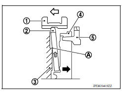
Operation Principle
- When the shift selector is moved to reverse position, 5th-reverse
coupling sleeve (1) slides in the reverse direction. (
 )
) - Synchronizer levers (2) with support point (A) at 5th-reverse
synchronizer hub (3) presses 5th-reverse baulk ring (4). (
 )
) - Friction that is generated at 5-reverse baulk ring presses synchronizer
lever on 5th-reverse coupling sleeve. (
 )
) - 5th-reverse coupling sleeve that is pressed by synchronizer lever stops the rotation of input shaft.
(5) : 5th input gear
 Precautions
Other materials:
Cleaning interior
Occasionally remove loose dust from the interior
trim, plastic parts and seats using a vacuum
cleaner or soft bristled brush. Wipe the vinyl and
leather surfaces with a clean, soft cloth dampened
in mild soap solution, then wipe clean with a
dry, soft cloth.
Regular care and cleaning is requ ...
Automatic speed control device (ASCD)
Automatic speed control device (ascd) : system diagram
NOTE:
Transmission range switch and TCM is also for A/T models.
Automatic speed control device (ascd) : system description
INPUT/OUTPUT SIGNAL CHART
Sensor
Input signal to ECM
ECM function
Actuator
Brake pedal ...
Categories
- Manuals Home
- Nissan Versa Owners Manual
- Nissan Versa Service Manual
- Video Guides
- Questions & Answers
- External Resources
- Latest Updates
- Most Popular
- Sitemap
- Search the site
- Privacy Policy
- Contact Us

0.0077