Nissan Versa (N17): Key interlock cable
Exploded View
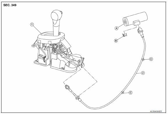
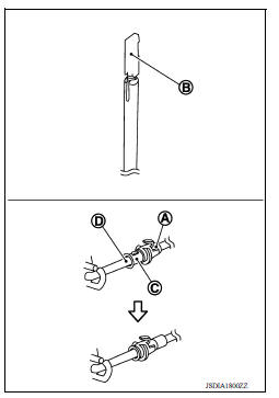
1. A/T shift selector assembly 2. Key interlock cable A: Key cylinder B: Lock plate C: Clip
Removal and Installation
CAUTION: Always apply the parking brake before performing removal and installation.
REMOVAL
- Move the shift selector to the "N" position.
- Remove the shift selector handle. Refer to TM "Disassembly and Assembly".
- Remove the center console. Refer to IP "Removal and Installation".
- Move the shift selector to the "P" position.
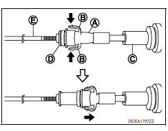
- Press the pawls (B) of the key interlock cable slider (A) while sliding it in the direction of the casing cap (C), and separate the adjusting holder (D) and slider.
(E) : Key interlock rod
- Remove the key interlock cable from the shift selector assembly.
- Remove the instrument lower panel LH. Refer to IP "Removal and Installation".
- Remove the steering column upper and lower covers. Refer to ST "Exploded View".
- Remove the center console lower (if equipped). Refer to IP "Removal and Installation".
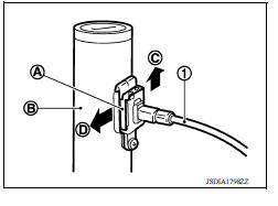
- Lift lock plate (A) in the direction of the arrow (
 C) and remove
in the direction of the arrow (
C) and remove
in the direction of the arrow (  D).
D). - Remove the key interlock cable from the key cylinder.
- Disengage the clips and remove the key interlock cable from the vehicle.
(1) : Key interlock cable
(B) : Key cylinder
INSTALLATION
Installation is in the reverse order of removal.
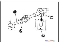
- Temporarily install the adjust holder (A) to the key interlock rod (B).
- Install the casing cap (C) to the cable bracket (D) on the shift selector assembly.
CAUTION:
- Do not bend or twist key interlock cable excessively when installing.
- After installing key interlock cable to cable bracket (D) on shift selector assembly, make sure casing cap (C) is firmly secured in cable bracket (D) on shift selector assembly.
- If casing cap (C) is loose [less than 39.2 N (4.0 kg, 8.8 lb) removing force], replace key interlock cable.
- Slide the slider (A) toward the key interlock rod (D) while pressing the pull lock (B) down to securely connect the adjust holder (C) with the key interlock rod (D).
CAUTION:
- Do not press tabs when holding slider (A).
- Do not apply any side-to-side force to key interlock rod (D) when sliding slider (A).
Inspection
INSPECTION AFTER INSTALLATION
- Check the A/T operation. If a malfunction is found, adjust the A/T position. Refer to TM "Inspection and Adjustment".
- Make sure the key can be removed only when the shift selector is in the "P" position.
- Make sure the ignition switch will not turn to LOCK position when the shift selector is not in the "P" position.
 Control cable
Exploded View 1. Bracket B 2. Lock plate 3. Transaxle assembly 4. Bracket A 5. Control cable 6. Shift selector assembly A: Manual lever B: Grommet Removal and Installation CAUTION: Always ap ...
TCM
Exploded View 1. TCM 2. Bracket 3. Clips Front Removal and Installation NOTE: When replacing the TCM and transaxle assembly as a set, replace the transaxle assembly first and then re ...
Other materials:
Additional service when replacing
ECM
Description
When replacing ECM, the following procedure must be performed.
PROGRAMMING OPERATION
NOTE:
After replacing with a blank ECM, programming is required to write ECM
information. Be sure to follow the procedure
to perform the programming.
Work Procedure
1.CHECK ECM PART NUMBER
Che ...
Removal and installation
ECM
Exploded View
1. ECM bracket 2. ECM
: Vehicle front
Removal and Installation
CAUTION: Perform ADDITIONAL SERVICE WHEN REPLACING ECM. Refer to
EC-122, "Work Procedure".
REMOVAL
Remove battery. Refer to PG, "Removal and Installation".
Remove IPDM E/R. Re ...
Categories
- Manuals Home
- Nissan Versa Owners Manual
- Nissan Versa Service Manual
- Video Guides
- Questions & Answers
- External Resources
- Latest Updates
- Most Popular
- Sitemap
- Search the site
- Privacy Policy
- Contact Us

0.005