Nissan Versa (N17): Crash zone sensor
Exploded View
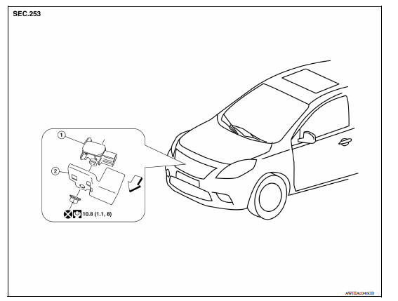
1. Crash zone sensor 2. Bracket A. Nut
 Front
Front
Removal and Installation
REMOVAL
WARNING:
- Before servicing, turn ignition switch OFF, disconnect battery negative terminal and wait three minutes or more.
- Do not use the air tools or electric tools for servicing.
CAUTION:
- Do not impact the crash zone sensor.
- Replace the crash zone sensor if it has been dropped or sustained an impact.
- Replace the crash zone sensor of deployed driver air bag and deployed passenger air bag.
- Remove the crash zone sensor nut, then remove the bracket and crash zone sensor from radiator support bracket in front of vehicle.
- Disconnect the harness connector from the crash zone sensor.
- Remove crash zone sensor.
INSTALLATION
Installation is in the reverse order of removal.
CAUTION:
- Make sure the locating pin on crash zone sensor is aligned with the cutout hole of the radiator support bracket before tightening nut.
- Do not use the old nut after removal, replace with new nut.
- Do not damage the harness while installing.
- If malfunction is detected by the air bag warning lamp, after repair or replacement of the malfunctioning parts, reset the memory using self-diagnosis or CONSULT. Refer to SRC "SRS Operation Check" or SRC "CONSULT Function (AIR BAG)".
- After the work is completed, check that no system malfunction is detected by air bag warning lamp.
 Side air bag module
Removal and Installation REMOVAL WARNING: Do not leave any objects (screwdrivers, tools, etc.) on the seat during seatback repair. It can lead to personal injury if the side air bag should accid ...
Side air bag (satellite) sensor
Removal and Installation Side air bag (satellite) sensor 1. Side air bag (satellite) sensor harness slide double locking type connector Front Front door (satellite) sensor 1. Front ...
Other materials:
Structure and operation
Sectional View
1. Clutch housing 2. 1st-2nd synchronizer hub assembly 3. 3rd-4th
synchronizer hub assembly
4. 5th input gear 5. 5th-reverse synchronizer hub assembly 6. 5th-reverse baulk
ring
7. 5th main gear 8. 4th main gear 9. 3rd main gear
10. 2nd main gear 11. 2nd double-cone synchr ...
Slip indicator lamp
Component Function Check
1.CHECK SLIP INDICATOR LAMP FUNCTION
Check that slip indicator lamp in combination meter turns ON for
approximately 2 seconds after ignition switch
is turned ON.
Is the inspection result normal?
YES >> Inspection End.
NO >> Proceed to diagnosis procedure. ...
Categories
- Manuals Home
- Nissan Versa Owners Manual
- Nissan Versa Service Manual
- Video Guides
- Questions & Answers
- External Resources
- Latest Updates
- Most Popular
- Sitemap
- Search the site
- Privacy Policy
- Contact Us

0.0104