Nissan Versa (N17): Diagnosis and repair workflow
Work Flow
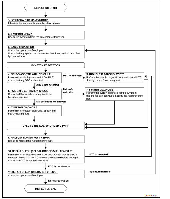
OVERALL SEQUENCE
DETAILED FLOW
1.INTERVIEW FOR MALFUNCTION
Interview the symptom to the customer.
>> GO TO 2.
2.SYMPTOM CHECK
Check the symptom from the customer's information.
>> GO TO 3.
3.BASIC INSPECTION
Check the operation of each part. Check that any symptom occurs other than the interviewed symptom.
>> GO TO 4.
4.SELF-DIAGNOSIS WITH CONSULT
Perform the self-diagnosis with CONSULT. Check that any DTC is detected.
Is any DTC detected?
YES >> GO TO 5.
NO >> GO TO 6.
5.TROUBLE DIAGNOSIS BY DTC
Perform the trouble diagnosis for the detected DTC. Specify the malfunctioning part.
>> GO TO 9.
6.FAIL-SAFE ACTIVATION CHECK
Check that the symptom is applied to the fail-safe activation.
Does the fail-safe activate?
YES >> GO TO 7.
NO >> GO TO 8.
7.SYSTEM DIAGNOSIS
Perform the system diagnosis for the system that the fail-safe activates. Specify the malfunctioning part.
>> GO TO 9.
8.SYMPTOM DIAGNOSIS
Perform the symptom diagnosis. Specify the malfunctioning part.
>> GO TO 9.
9.MALFUNCTION PART REPAIR
Repair or replace the malfunctioning part.
>> GO TO 10.
10.REPAIR CHECK (SELF-DIAGNOSIS WITH CONSULT)
Perform the self-diagnosis with CONSULT. Check that any DTC is not detected. Erase DTC if DTC is detected before the repair. Check that DTC is not detected again.
Is any DTC detected?
YES >> GO TO 5.
NO >> GO TO 11.
11.REPAIR CHECK (OPERATION CHECK)
Check the operation of each part.
Does it operate normally?
YES >> INSPECTION END
NO >> GO TO 3.
DTC/CIRCUIT DIAGNOSIS
 System
Other materials:
Insufficient cooling
Description
Symptom
Insufficient cooling
No cool air comes out. (Air flow volume is normal.)
Diagnosis Procedure
NOTE:
Perform self-diagnosis with CONSULT before performing symptom diagnosis. If any
malfunction result or DTC
is detected, perform the corresponding diagnosis.
1.CHE ...
Door hinge
DOOR HINGE : Removal and Installation
CAUTION:
Use two people when removing or installing rear door due to its
heavy weight.
When removing and installing rear door assembly, support door
using a suitable tool.
REMOVAL
Remove rear door assembly. Refer to DLK "DOOR ASSEMBLY : ...
Categories
- Manuals Home
- Nissan Versa Owners Manual
- Nissan Versa Service Manual
- Video Guides
- Questions & Answers
- External Resources
- Latest Updates
- Most Popular
- Sitemap
- Search the site
- Privacy Policy
- Contact Us

0.0058