Nissan Versa (N17): Camshaft valve clearance
Inspection and Adjustment
INSPECTION
Perform inspection as follows after removal, replacement or installation of camshaft or valverelated parts, or if there are unusual engine conditions regarding valve clearance.
- Remove rocker cover.
- Measure the valve clearance with the following procedure:
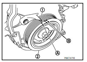
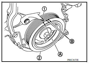
- Set No. 1 cylinder at TDC of its compression stroke.
- Rotate crankshaft pulley (2) clockwise and align TDC mark (no paint) (A) to timing indicator (1) on front cover.
(B) : White paint mark (Not used for service)
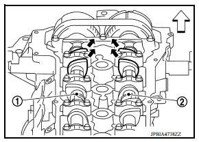
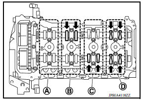
- At the same time, check that both intake and exhaust cam
lobes of No. 1 cylinder face inside (
 ) as shown.
(1) : Camshaft (INT)
(2) : Camshaft (EXH)
 : Engine front
- If the lobes do not face inside, rotate the crankshaft pulley 360 degrees to align as shown.
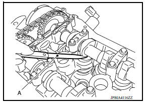
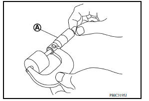
- Use a feeler gauge (A) to measure the clearance between the valve lifter and camshaft.
- Refer to the figure. Using a feeler gauge, measure the valve
clearances at locations marked "×" in the table below [also
shown with black arrow ( )].
(A) : No. 1 cylinder
(B) : No. 2 cylinder
(C) : No. 3 cylinder
(D) : No. 4 cylinder
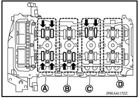
| Measuring position | No. 1 CYL. | No. 2 CYL. | No. 3 CYL. | No. 4 CYL. | |
| No. 1 cylinder at compression TDC | EXH | x | x | ||
| INT | x | x | |||
- Set No. 4 cylinder at TDC of its compression stroke.
- Rotate crankshaft pulley (2) one revolution (360 degrees) and align TDC mark (no paint) (A) to timing indicator (1) on front cover.
(B) : White paint mark (Not use for service)
- Refer to the figure. Using a feeler gauge, measure the valve
clearances at locations marked "×" in the table below [also
shown with black arrow (
 )].
)].
(A) : No. 1 cylinder
(B) : No. 2 cylinder
(C) : No. 3 cylinder
(D) : No. 4 cylinder
| Measuring position | No. 1 CYL. | No. 2 CYL. | No. 3 CYL. | No. 4 CYL. | |
| No. 4 cylinder at compression TDC | EXH | x | x | ||
| INT | x | x | |||
- If out of the specifications, adjust as necessary. Refer to "ADJUSTMENT".
ADJUSTMENT
NOTE:
Proper valve clearance is obtained by selecting the correct valve lifter head thickness.
- Remove camshaft.
- Remove valve lifters from the locations that are out of specification.
- Measure the center thickness of the removed valve lifters with a micrometer (A).
- Use the equation below to calculate valve lifter thickness for replacement.
Valve lifter thickness calculation: t = t1 + (C1 - C2)
t = Valve lifter thickness to be replaced
t1 = Removed valve lifter thickness
C1 = Measured valve clearance
C2 = Standard valve clearance:
Intake : 0.30 mm (0.012 in)
Exhaust : 0.33 mm (0.013 in)
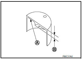
- Thickness of new valve lifter (B) can be identified by stamp mark (A) on the under side of the lifter.
NOTE:
Available thickness of valve lifter: 26 sizes range 3.00 to 3.50 mm (0.1181 to 0.1378 in) in increments of 0.02 mm (0.0008 in) when manufactured at factory.
- Stamp mark "302" indicates 3.02 mm (0.1189 in) in thickness.
- Install the correct thickness valve lifter.
- Install camshaft.
- Install timing chain and related parts.
- Manually rotate crankshaft pulley a few rotations.
- Check that valve clearances are within specification. Refer to "INSPECTION".
- Install remaining parts in the reverse order of removal.
- Warm up the engine, and check for unusual noise and vibration.
 Preparation
Special Service Tools The actual shapes of KentMoore tools may differ from those of special service tools illustrated here. Tool number (KentMoore No.) Tool name Description ...
Compression pressure
Inspection Warm up engine and then turn it off. Release fuel pressure. Remove ignition coil and spark plug from each cylinder. Connect engine tachometer (not required in use of CONSULT). ...
Other materials:
OFF Position warning does not operate
Diagnosis Procedure
1.CHECK DTC WITH BCM
Check that DTC is not detected with BCM
Is the inspection result normal?
YES >> GO TO 2.
NO >> Perform trouble diagnosis relevant to DTC indicated.
2.CHECK DTC WITH COMBINATION METER
Check that DTC is not detected with combination meter
...
Audio unit
Removal and Installation
REMOVAL
1. Remove cluster lid C. Refer to IP "Removal and Installation".
2. Remove the audio unit screws (A).
3. Pull the audio unit out.
4. Disconnect the harness connectors from the audio unit and
remove.
5. Remove the audio unit bracket screws (A) and t ...
Categories
- Manuals Home
- Nissan Versa Owners Manual
- Nissan Versa Service Manual
- Video Guides
- Questions & Answers
- External Resources
- Latest Updates
- Most Popular
- Sitemap
- Search the site
- Privacy Policy
- Contact Us

0.0093