Nissan Versa (N17): Diagnosis and repair workflow
Work Flow
OVERALL SEQUENCE
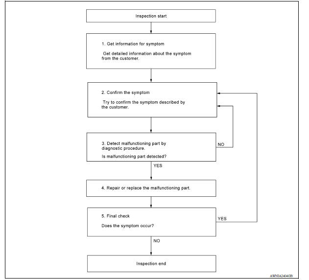
DETAILED FLOW
1.GET INFORMATION FOR SYMPTOM
Get detailed information from the customer about the symptom (the condition and the environment when the incident/malfunction occurred).
>> GO TO 2.
2.CONFIRM THE SYMPTOM
Try to confirm the symptom described by the customer. Verify relation between the symptom and the condition when the symptom is detected. Refer to AV "Symptom Table".
>> GO TO 3.
3.DETECT MALFUNCTIONING PART BY DIAGNOSTIC PROCEDURE
Inspect according to Diagnostic Procedure of the system.
Is malfunctioning part detected?
YES >> GO TO 4.
NO >> GO TO 2.
4.REPAIR OR REPLACE THE MALFUNCTIONING PART
1. Repair or replace the malfunctioning part.
2. Reconnect parts or connectors disconnected during Diagnostic Procedure.
>> GO TO 5.
5.FINAL CHECK
Refer to confirmed symptom in step 2, and make sure that the symptom is not detected.
Has the symptom been repaired?
YES >> Inspection End.
NO >> GO TO 2.
DTC/CIRCUIT DIAGNOSIS
 Diagnosis system (bluetooth control
unit)
Diagnosis system (bluetooth control
unit)
Diagnosis Description The Bluetooth control unit has two diagnostic checks. The first diagnostic check is performed automatically every ignition cycle during control unit initialization. The sec ...

Other materials:
4-speed automatic transmission fluid (ATF) (if so equipped)
When checking or replacement of automatic
transmission fluid is required, it is recommended
that you visit a NISSAN dealer for servicing.
WARNING
When the engine is running, keep
hands, jewelry and clothing away from
any moving parts such as the cooling
fan and drive belts
Automatic t ...
Road wheel
Inspection
ALUMINUM WHEEL
Check tires for wear and improper inflation.
Check wheels for deformation, cracks and other damage. If deformed,
remove wheel and check wheel
runout.
a. Remove tire from aluminum wheel and mount wheel on a balancer machine.
b. Set dial indicator as shown.
c ...
Categories
- Manuals Home
- Nissan Versa Owners Manual
- Nissan Versa Service Manual
- Video Guides
- Questions & Answers
- External Resources
- Latest Updates
- Most Popular
- Sitemap
- Search the site
- Privacy Policy
- Contact Us

0.0049