Nissan Versa (N17): P0720 Output speed sensor
DTC Logic
DTC DETECTION LOGIC
| DTC | Trouble diagnosis name | DTC detection condition | Possible causes |
| P0720 | Output Speed Sensor Circuit | The output speed sensor value is less than
150 rpm continuously for 10 seconds or more
under the following diagnosis conditions: - Diagnosis conditions - Selector lever: "D", "L" or "R" position - Auxiliary gearbox shifting is not in progress. - When the "D" position switch, "L" position switch or "R" position switch is ON, the output speed has not experienced 250 rpm or more. - After shifting the selector lever, the input speed has experienced less than 300 rpm. - Secondary pulley speed: 1,500 rpm or more - TCM power supply voltage: More than 11 V |
- Harness or connector
(Output speed sensor circuit is open or
shorted) - Output speed sensor |
| The output speed sensor value is 90 rpm or
less continuously for 500 msec or more under
the following diagnosis conditions: - Diagnosis conditions - 10-msec-ago output speed: 730 rpm or more - TCM power supply voltage: More than 11 V |
DTC CONFIRMATION PROCEDURE
CAUTION: Be careful of the driving speed.
1.PREPARATION BEFORE WORK
If another "DTC CONFIRMATION PROCEDURE" occurs just before, turn ignition switch OFF and wait for at least 10 seconds, then perform the next test.
>> GO TO 2.
2.CHECK DTC DETECTION
- Start the engine.
- Drive the vehicle.
- Maintain the following conditions for 10 seconds or more.
- Stop the vehicle.
- Check the first trip DTC.
Selector lever : "D" position Vehicle speed : 55 km/h (34 MPH) or more
Is "P0720" detected?
YES >> Go to TM "Diagnosis Procedure".
NO >> INSPECTION END
Diagnosis Procedure
1.CHECK OUTPUT SPEED SENSOR POWER CIRCUIT
- Turn ignition switch OFF.
- Disconnect output speed sensor connector.
- Turn ignition switch ON.
- Check voltage between output speed sensor harness connector terminal and
ground.
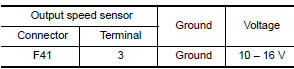
Is the inspection result normal?
YES >> GO TO 2.
NO >> GO TO 6.
2.CHECK OUTPUT SPEED SENSOR GROUND CIRCUIT
Check continuity between output speed sensor harness connector terminal and
ground. 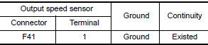
Is the inspection result normal?
YES >> GO TO 3.
NO >> Repair or replace malfunctioning parts.
3.CHECK CIRCUIT BETWEEN OUTPUT SPEED SENSOR AND TCM (PART 1)
- Turn ignition switch OFF.
- Disconnect TCM connector.
- Check continuity between output speed sensor harness connector terminal
and TCM harness connector
terminal.
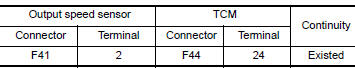
Is the inspection result normal?
YES >> GO TO 4.
NO >> Repair or replace malfunctioning parts.
4.CHECK CIRCUIT BETWEEN OUTPUT SPEED SENSOR AND TCM (PART 2)
Check continuity between output speed sensor harness connector terminal and
ground. 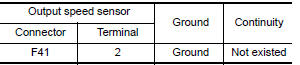
Is the inspection result normal?\
YES >> GO TO 5.
NO >> Repair or replace malfunctioning parts.
5.CHECK TCM INPUT SIGNALS
- Connect all of disconnected connectors.
- Lift the vehicle.
- Start the engine.
- Check frequency of output speed sensor.
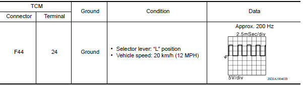
Is the inspection result normal?
YES >> Check intermittent incident. Refer to GI "Intermittent Incident".
NO >> Replace output speed sensor. Refer to TM "Removal and Installation".
6.CHECK CIRCUIT BETWEEN IPDM E/R AND OUTPUT SPEED SENSOR (PART 1)
- Disconnect IPDM E/R connector.
- Check continuity between IPDM E/R harness connector terminal and output
speed sensor harness connector
terminal.
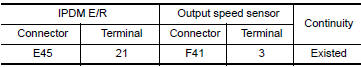
Is the check result normal?
YES >> GO TO 7.
NO >> Repair or replace malfunctioning parts.
7.CHECK CIRCUIT BETWEEN IPDM E/R AND OUTPUT SPEED SENSOR (PART 2)
Check continuity between IPDM E/R harness connector terminal and ground. 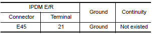
Is the check result normal?
YES >> GO TO 8.
NO >> Repair or replace malfunctioning parts.
8.DETECT MALFUNCTIONING ITEMS
Check the following items:
- Harness open circuit or short circuit between ignition switch and IPDM E/R. Refer to PG "Wiring Diagram - Ignition Power Supply -".
- 10A fuse (No.49, IPDM E/R). Refer to PG "IPDM E/R Terminal Arrangement".
- IPDM E/R
Is the check result normal?
YES >> Check intermittent incident. Refer to GI "Intermittent Incident".
NO >> Repair or replace malfunctioning parts.
 P0715 Input speed sensor A
Other materials:
Exhaust system
Exploded View
1. Heated oxygen sensor 2 2. Catalyst cover (upper) 3. Seal bearing
4. Catalyst cover (lower) 5. Spring 6. Spring
7. Mounting rubber 8. Main muffler 9. Ring gasket
10. Center muffler 11. Mounting rubber 12. Seal bearing
13. Exhaust front tube
Removal and Installation
WARNIN ...
Diagnosis system [abs actuator
and electric unit (control unit)]
CONSULT Function (ABS)
APPLICATION ITEMS
CONSULT can display each diagnostic item using the following direct
diagnostic modes.
ECU IDENTIFICATION
ABS actuator and electric unit (control unit) part number is displayed.
SELF DIAGNOSTIC RESULT
Operation Procedure
Before p ...
Categories
- Manuals Home
- Nissan Versa Owners Manual
- Nissan Versa Service Manual
- Video Guides
- Questions & Answers
- External Resources
- Latest Updates
- Most Popular
- Sitemap
- Search the site
- Privacy Policy
- Contact Us

0.0055