Nissan Versa (N17): B2618 BCM
DTC Logic
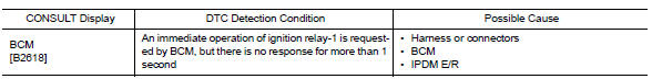
DTC DETECTION LOGIC
NOTE:
- If DTC B2618 is displayed with DTC U1000, first perform the trouble diagnosis for DTC U1000. Refer to PCS "DTC Logic".
- If DTC B2618 is displayed with DTC U1010, first perform the trouble
diagnosis for DTC U1010. Refer to
PCS "DTC Logic".
DTC CONFIRMATION PROCEDURE
1. PERFORM SELF DIAGNOSTIC RESULT
1. Turn ignition switch ON under the following conditions, and wait for at least 1 second.
- CVT selector lever is in the P (park) or N (neutral) position.
- Release brake pedal
2. Perform self diagnostic result.
Is DTC B2618 detected?
YES >> Refer to PCS "Diagnosis Procedure".
NO >> Inspection End.
Diagnosis Procedure
Regarding Wiring Diagram information, refer to PCS "Wiring Diagram".
1.CHECK IGNITION RELAY-1 CONTROL SIGNAL
Check voltage between BCM harness connector and ground.
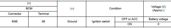
Is the inspection result normal?
YES >> Replace BCM. Refer to BCS "Removal and Installation".
NO >> GO TO 2.
2.CHECK IGNITION RELAY-1 CONTROL SIGNAL CIRCUIT
1. Turn ignition switch OFF.
2. Disconnect BCM connector and IPDM E/R.
3. Check continuity between BCM harness connector and IPDM E/R harness
connector.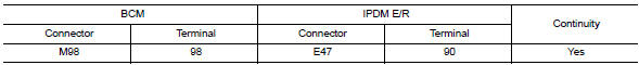
4. Check continuity between BCM harness connector and ground.
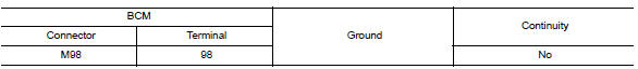
Is the inspection result normal?
YES >> GO TO 3.
NO >> Repair or replace harness.
3.CHECK VOLTAGE OF IGNITION RELAY-1 CONTROL SIGNAL CIRCUIT (IPDM E/R SIDE)
1. Connect IPDM E/R connector.
2. Check voltage between IPDM E/R harness connector and ground.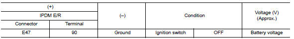
Is the inspection result normal?
YES >> Replace BCM. Refer to BCS "Removal and Installation".
NO >> Replace IPDM E/R.
 B2616 Ignition relay circuit
Other materials:
Diagnosis sensor unit
Removal and Installation
1. Diagnosis sensor unit 2. Diagnosis sensor unit harness bracket
Front
REMOVAL
WARNING:
When replacing the air bag diagnosis sensor unit, always check with the parts
department for he latest
parts information. Installing an incorrect air bag diagnosis sensor uni ...
NATS antenna AMP
Removal and Installation
NOTE:
If NATS antenna amp. is not installed correctly, NVIS (NATS) system
will not operate properly and "SELFDIAG
RESULTS" on CONSULT screen will show "LOCK MODE" or "CHAIN OF IMMU-KEY".
Initialization is not necessary when only th ...
Categories
- Manuals Home
- Nissan Versa Owners Manual
- Nissan Versa Service Manual
- Video Guides
- Questions & Answers
- External Resources
- Latest Updates
- Most Popular
- Sitemap
- Search the site
- Privacy Policy
- Contact Us

0.0065