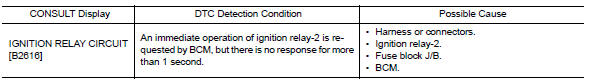
Nissan Versa (N17): B2616 Ignition relay circuit
DTC Logic
DTC DETECTION LOGIC
DTC CONFIRMATION PROCEDURE
1. PERFORM SELF DIAGNOSTIC RESULT
1. Turn ignition switch ON under the following conditions, and wait for at least 1 second.
- CVT selector lever is in the P (park) or N (neutral) position.
- Release brake pedal
2. Perform self diagnostic result.
Is DTC B2616 detected?
YES >> Refer to PCS "Diagnosis Procedure".
NO >> Inspection End.
Diagnosis Procedure
Regarding Wiring Diagram information, refer to PCS "Wiring Diagram".
1. CHECK IGNITION RELAY-2 POWER SUPPLY CIRCUIT
1. Turn ignition switch OFF.
2. Disconnect BCM connector M98.
3. Check continuity between ignition relay-2 connector J-3 terminal 1 and BCM
connector M98 terminal 99.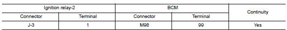
4. Check continuity between ignition relay-2 connector J-3 terminal 1 and
ground.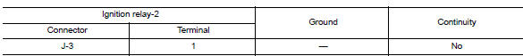
Is the inspection result normal?
YES >> GO TO 2.
NO >> Repair or replace harness or connectors.
2. CHECK IGNITION RELAY-2 GROUND CIRCUIT
1. Check continuity between ignition relay-2 connector J-3 terminal 2 and
ground.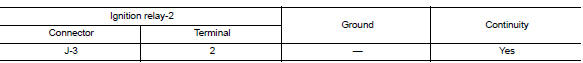
Is the inspection result normal?
YES >> GO TO 3.
NO >> Repair or replace harness or connectors.
3. CHECK IGNITION RELAY-2
Perform the relay component inspection. Refer to PCS "Component Inspection".
Is the inspection result normal?
YES >> GO TO 4.
NO >> Replace ignition relay-2.
4. CHECK IGNITION RELAY-2 POWER SUPPLY (BCM)
Check voltage between BCM connector M98 terminal 99 and ground.
Is the inspection result normal?
YES >> Refer to GI "Intermittent Incident".
NO >> Replace BCM. Refer to BCS "Removal and Installation".
Component Inspection
1.CHECK IGNITION RELAY
1. Turn ignition switch OFF.
2. Remove ignition relay.
3. Check the continuity between ignition relay terminals.
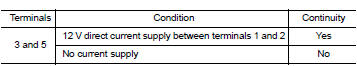
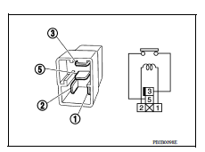
Is the inspection result normal?
YES >> Inspection End.
NO >> Replace ignition relay
 B2615 Blower relay circuit
Other materials:
Drive belt idler pulley
Exploded View
1. Generator bracket 2. Center shaft 3. Spacer
4. Adjusting bolt 5. Washer 6. Idler pulley
7. Plate
Removal and Installation
REMOVAL
Remove the fender protector (RH).
Remove the air duct inlet assembly.
Remove drive belt.
Remove the lock nut, and then remove the pl ...
Rear regulator
Exploded View
1. Rear door panel 2. Sealing screen 3. Rear door sash
4. Rear power window motor 5. Regulator assembly 6. Partition sash
7. Partition glass 8. Rear door glass 9. Partition weather-strip
10. Rear door glass run 11. Regulator seal (manual window) 12. Retaining clip
(manual win ...
Categories
- Manuals Home
- Nissan Versa Owners Manual
- Nissan Versa Service Manual
- Video Guides
- Questions & Answers
- External Resources
- Latest Updates
- Most Popular
- Sitemap
- Search the site
- Privacy Policy
- Contact Us

0.006