Nissan Versa (N17): B26F1 Ignition relay
DTC Logic
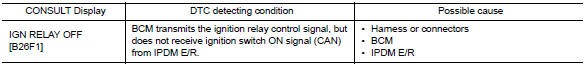
DTC DETECTION LOGIC
DTC CONFIRMATION PROCEDURE
1.PERFORM DTC CONFIRMATION PROCEDURE
1. Turn ignition switch ON, and wait for 2 seconds or more.
2. Check "Self-diagnosis result" with CONSULT.
Is DTC detected?
YES >> Go to PCS "Diagnosis Procedure".
NO >> Inspection End.
Diagnosis Procedure
Regarding Wiring Diagram information, refer to PCS "Wiring Diagram".
1.CHECK IPDM E/R SELF-DIAGNOSTIC RESULT
1. Turn ignition switch ON.
2. Erase the DTC of IPDM E/R.
3. Turn ignition switch OFF.
4. Turn ignition switch ON and check the DTC again.
Is DTC detected?
YES >> Repair or replace the malfunctioning part. Refer to BCS "DTC Index".
NO >> GO TO 2.
2.CHECK IGNITION RELAY-1 CONTROL SIGNAL (IPDM E/R)
Check voltage between BCM harness connector and ground.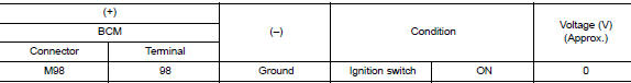
Is the inspection result normal?
YES >> GO TO 3.
NO >> Replace BCM. Refer to BCS "Removal and Installation".
3.CHECK IGNITION RELAY-1 CONTROL SIGNAL CIRCUIT (IPDM E/R)
1. Turn ignition switch OFF.
2. Disconnect BCM and IPDM E/R connectors.
3. Check continuity between BCM harness connector and IPDM E/R harness
connector.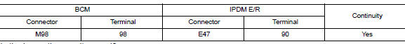
Is the inspection result normal?
YES >> Replace IPDM E/R.
NO >> Repair or replace harness.
 B261A Push-button ignition switch
Other materials:
Spark plug
Exploded View
1. Ignition coil 2. Spark plug
Removal and Installation
REMOVAL
1. Remove ignition coil.
CAUTION:
Do not drop or shock ignition coil.
2. Remove spark plug using a suitable tool.
Diameter (a) : 14 mm (0.55 in)
CAUTION:
Do not drop or shock spark plug.
INSPECTION AFTER REM ...
Passenger air bag module
Exploded View
1. Passenger air bag module 2. Instrument panel assembly
Pawl
Removal and Installation
WARNING:
Before servicing, turn ignition switch OFF, disconnect both the
battery negative and positive terminals,
then wait at least three minutes.
Always work from the side of ai ...
Categories
- Manuals Home
- Nissan Versa Owners Manual
- Nissan Versa Service Manual
- Video Guides
- Questions & Answers
- External Resources
- Latest Updates
- Most Popular
- Sitemap
- Search the site
- Privacy Policy
- Contact Us

0.0077