Nissan Versa (N17): Diagnosis system [abs actuator and electric unit (control unit)]
CONSULT Function (ABS)
APPLICATION ITEMS
CONSULT can display each diagnostic item using the following direct
diagnostic modes. 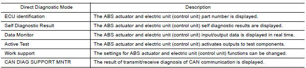
ECU IDENTIFICATION
ABS actuator and electric unit (control unit) part number is displayed.
SELF DIAGNOSTIC RESULT
Operation Procedure
- Before performing the self-diagnosis, start engine and drive vehicle at 30 km/h (19 MPH) or more for approximately 1 minute.
How To Erase Self Diagnostic Result
- After erasing DTC memory, start engine and drive vehicle at 30 km/h (19 MPH) or more for approximately 1 minute as the final inspection, and make sure that the ABS warning lamp, VDC OFF indicator lamp, SLIP indicator lamp and brake warning lamp turn OFF.
CAUTION: If memory cannot be erased, perform applicable diagnosis.
NOTE:
- When the wheel sensor malfunctions, after inspecting the wheel sensor system, the ABS warning lamp, SLIP indicator lamp and brake warning lamp will not turn OFF even when the system is normal, unless the vehicle is driven at approximately 30 km/h (19 MPH) or more for approximately 1 minute.
- Brake warning lamp will turn ON in case of parking brake operation (when switch is ON) or of brake fluid level switch operation (when brake fluid is insufficient).
- VDC OFF switch should not stay in ON position.
Display Item List
Refer to BRC "DTC Index".
DATA MONITOR
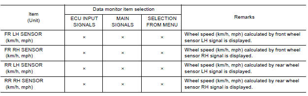
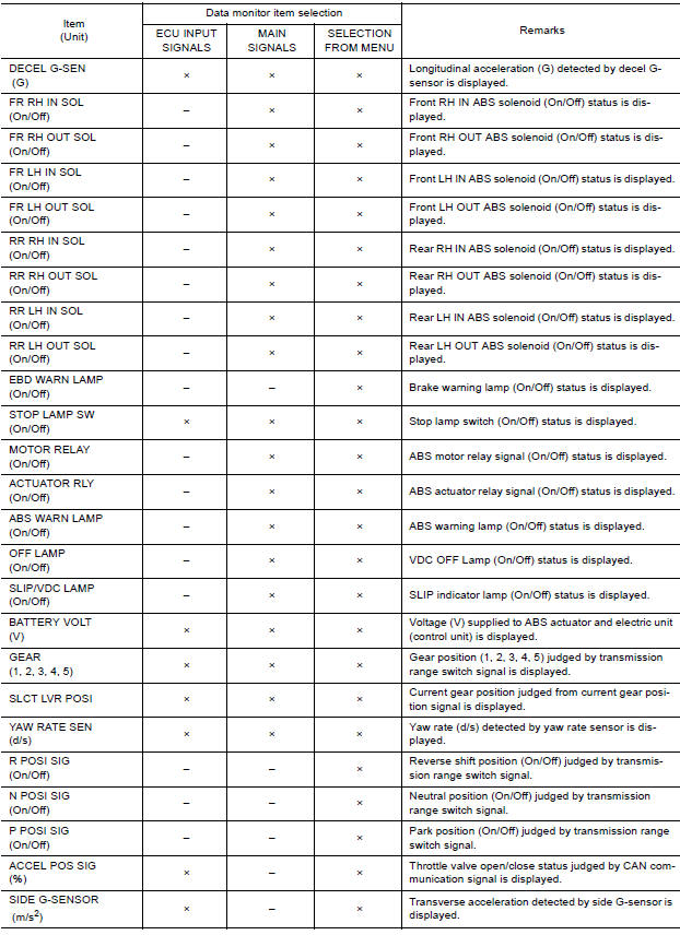
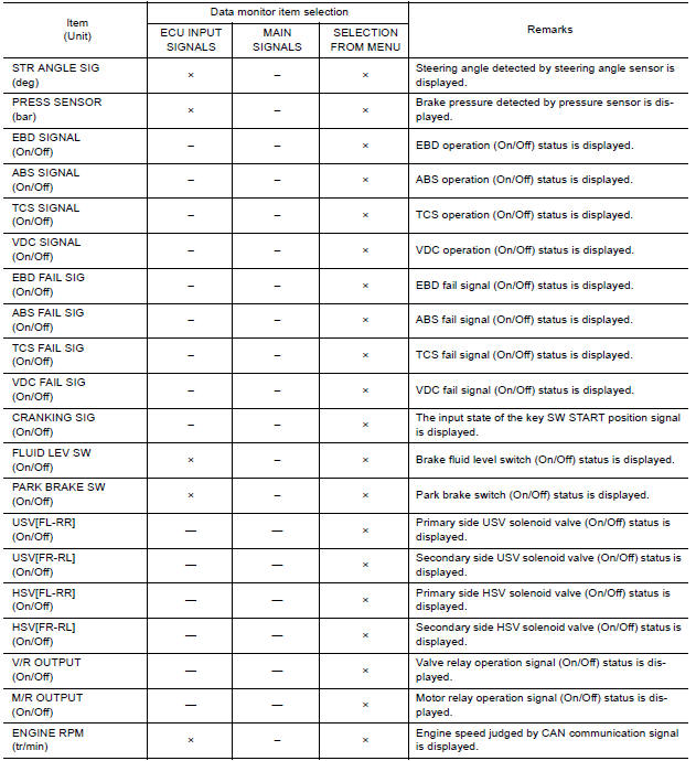
×: Applicable
-: Not applicable
ACTIVE TEST MODE
CAUTION:
- Do not perform active test while driving vehicle.
- Make sure to completely bleed air from brake system.
- The active test cannot be performed with the ABS warning lamp, VDC OFF indicator lamp, SLIP indicator lamp or brake warning lamp on.
- ABS warning lamp, VDC OFF indicator lamp, SLIP indicator lamp and brake warning lamp turn on during active test.
NOTE:
- When active test is performed while depressing the pedal, the pedal depression amount will change. This is normal.
- "TEST IS STOPPED" is displayed 10 seconds after operation start.
- After "TEST IS STOPPED" is displayed, to perform test again, touch BACK.
Test Item
ABS SOLENOID VALVE
- Select "Up", "Keep" and "Down". Then use screen monitor to check that solenoid valve operates as shown in the table below.
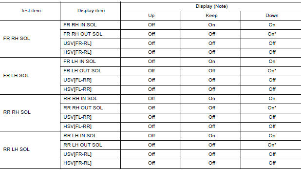
*: On for 1 to 2 seconds after the select, and then Off.
NOTE: A brief moment of On/Off condition occurs every 20 seconds after ignition switch turned ON. This is not malfunction because it is an operation for checking.
ABS SOLENOID VALVE (ACT)
Select "Up", "ACT UP" and "ACT KEEP". Then use screen monitor to check that solenoid valve operates as shown in the table below.
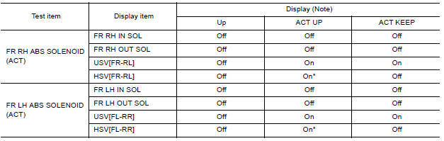
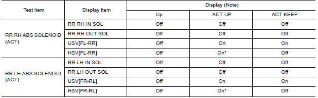
*: On for 1 to 2 seconds after the select, and then Off.
NOTE: A brief moment of On/Off condition occurs every 20 seconds after ignition switch turned ON. This is not malfunction because it is an operation for checking.
ABS MOTOR
- Select "On" and "Off". Make sure motor relay and actuator relay operates as shown in table below.
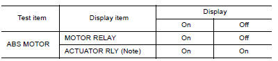
NOTE: A brief moment of On/Off condition occurs every 20 seconds after ignition switch turned ON. This is not malfunction because it is an operation for checking.
WORK SUPPORT
| Conditions | Description |
| ST ANGLE SENSOR ADJUSTMENT | Steering angle sensor neutral position adjustment can be performed.
Refer to BRC "Work Procedure". |
ECU DIAGNOSIS INFORMATION
 VDC/TCS/ABS
VDC/TCS/ABS : System Diagram ...

Other materials:
Wiper and washer switch
Switch operation
Type A (if so equipped)
The windshield wiper and washer operates when
the ignition switch is in the ON position.
Push the lever down to operate the wiper at the
following speed:
Intermittent (INT) - intermittent operation
can be adjusted by turning the knob toward
...
Fuel-filler door
Opener operation
The fuel-filler door release is located below the
instrument panel. To open the fuel-filler door, pull
the release. To lock, close the fuel-filler door
securely.
Fuel-filler cap
WARNING
Gasoline is extremely flammable and
highly explosive under certain conditions.
...
Categories
- Manuals Home
- Nissan Versa Owners Manual
- Nissan Versa Service Manual
- Video Guides
- Questions & Answers
- External Resources
- Latest Updates
- Most Popular
- Sitemap
- Search the site
- Privacy Policy
- Contact Us

0.0048