
Nissan Versa (N17): Differential side oil seal
Exploded View
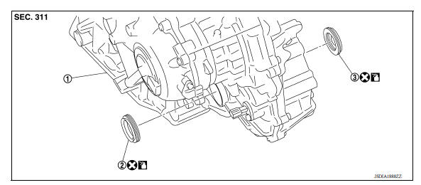
1. Transaxle assembly 2. Differential side oil seal (left side) 3.
Differential side oil seal (right side)
 Front
Front  Genuine
NISSAN CVT Fluid NS-3
Genuine
NISSAN CVT Fluid NS-3
Removal and Installation
NOTE: When removing components such as hoses, tubes/lines, etc., cap or plug openings to prevent fluid from spilling.
REMOVAL
- Remove the front drive shaft from the transaxle assembly. Refer to FAX "Removal and Installation"
- Remove the differential side oil seal using suitable tool.
CAUTION: When removing the differential side oil seal, be careful not to scratch the oil seal mating surfaces of the transaxle case and converter housing.
INSTALLATION
- Drive the differential side oil seal into the transaxle case side (A) and converter housing side (B) using suitable tool to the specified dimension.
CAUTION:
- Be careful not to scratch the lip of the differential side oil seal when press-fitting it.
- Do not reuse differential side oil seal.
- Apply Genuine NISSAN CVT Fluid NS-3 to the differential side oil seal lip and around the oil seal.
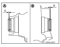
Dimension (C) : 1.8 +- 0.5 mm (0.071 +- 0.020 in).
Dimension (D) : 1.8 +- 0.5 mm (0.071 +- 0.020 in).
2. Install the front drive shaft. Refer to FAX "Removal and Installation".
Inspection and Adjustment
INSPECTION AFTER INSTALLATION
Check for CVT fluid leakage. Refer to TM "Inspection".
ADJUSTMENT AFTER INSTALLATION
Adjust the CVT fluid level. Refer to TM "Adjustment".
 Output speed sensor
Exploded View 1. Transaxle assembly 2. Output speed sensor 3. O-ring Front Genuine NISSAN CVT Fluid NS-3 Removal and Installation REMOVAL Disconnect the harness connector from output s ...
Water hose
Exploded View 1. Hose clamp 2. Water hose A 3. Bracket 4. Heater thermostat 5. Water hose B 6. Water hose C 7. Water bypass pipe 8. Hose clamp 9. Heater hose 9. Water hose D A. Water outlet B. ...
Other materials:
Precautions when starting and driving
WARNING
Do not leave children or adults who
would normally require the assistance
of others alone in your vehicle. Pets
should also not be left alone. They
could accidentally injure themselves or
others through inadvertent operation of
the vehicle. Also, on hot, sunny days,
tempera ...
Oil pan (lower)
Exploded View
1. Rear oil seal 2. Oring 3. Oil pan (upper) 4. Oil pump chain tensioner
(for oil pump drive chain) 5. Oil pump drive chain 6. Crankshaft key 7.
Crankshaft sprocket 8. Oil pump sprocket 9. Oil pump 10. Oring 11. Oring 12.
Oil pan drain plug 13. Drain plug washer 14. Oil pan ...
Categories
- Manuals Home
- Nissan Versa Owners Manual
- Nissan Versa Service Manual
- Video Guides
- Questions & Answers
- External Resources
- Latest Updates
- Most Popular
- Sitemap
- Search the site
- Privacy Policy
- Contact Us

0.0062