Nissan Versa (N17): Door switch
Description
Detects door open/close condition.
Component Function Check
1.CHECK FUNCTION
With CONSULT
Check door switches DOOR SW-DR, DOOR SW-AS, DOOR SW-RL, DOOR SW-RR in Data
Monitor mode
with CONSULT. 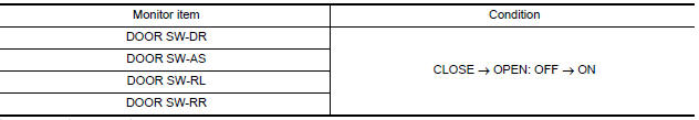
Is the inspection result normal?
YES >> Door switch is OK.
NO >> Refer to DLK "Diagnosis Procedure".
Diagnosis Procedure
Regarding Wiring Diagram information, refer to DLK "Wiring Diagram".
1.CHECK DOOR SWITCH INPUT SIGNAL
- Turn ignition switch OFF.
- Check signal between BCM connector and ground with oscilloscope.
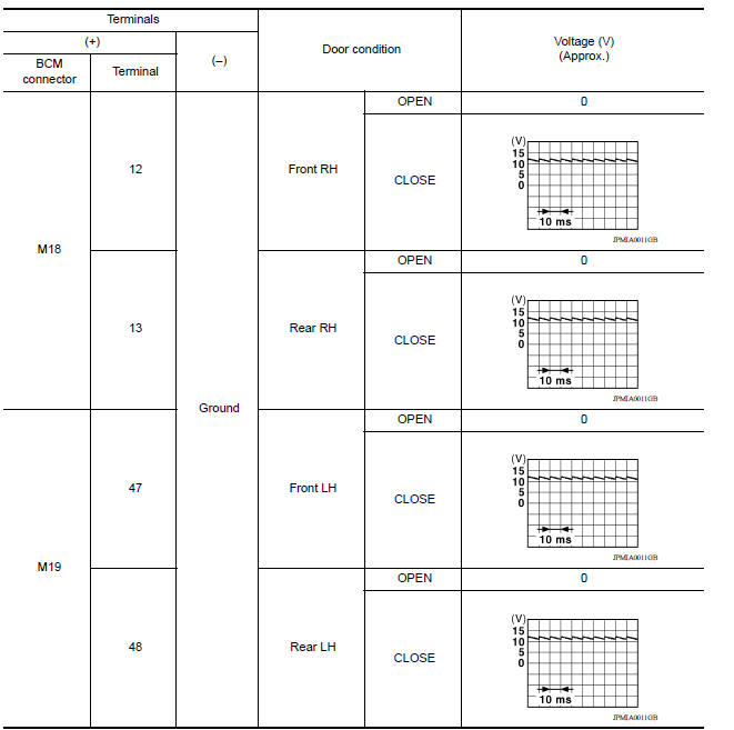
Is the inspection result normal?
YES >> GO TO 4
NO >> GO TO 2
2.CHECK DOOR SWITCH CIRCUIT
- Disconnect BCM connector.
- Check continuity between BCM connector and door switch connector.
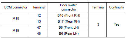
- Check continuity between BCM connector and ground.
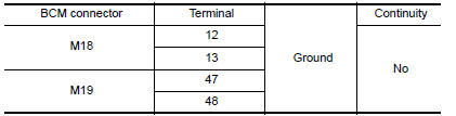
Is the inspection result normal?
YES >> GO TO 3
NO >> Repair or replace harness between BCM and door switch.
3.CHECK DOOR SWITCH
Refer to DLK "Component Inspection".
Is the inspection result normal?
YES >> GO TO 4
NO >> Replace malfunctioning door switch.
4.CHECK INTERMITTENT INCIDENT
Refer to GI "Intermittent Incident".
>> Inspection End.
Component Inspection
1.CHECK DOOR SWITCH
- Turn ignition switch OFF.
- Disconnect door switch connector.
- Check door switch.
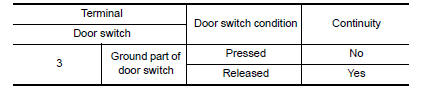
Is the inspection result normal?
YES >> Inspection End.
NO >> Replace malfunctioning door switch.
 Power supply and ground circuit
Diagnosis Procedure Regarding Wiring Diagram information, refer to BCS "Wiring Diagram". 1.CHECK FUSES AND FUSIBLE LINK Check that the following fuses and fusible link are not blown. ...

Other materials:
Specifications
Engine
This spark ignition system complies with the Canadian standard ICES-002.
Wheels and tires
Dimensions and weights
...
P0733 3GR Incorrect ratio
Description
This malfunction is detected when the A/T does not shift into 3GR position as
instructed by TCM. This is not
only caused by electrical malfunction (circuits open or shorted) but by
mechanical malfunction such as control
valve sticking, improper solenoid valve operation, etc.
DTC ...
Categories
- Manuals Home
- Nissan Versa Owners Manual
- Nissan Versa Service Manual
- Video Guides
- Questions & Answers
- External Resources
- Latest Updates
- Most Popular
- Sitemap
- Search the site
- Privacy Policy
- Contact Us

0.0055