Nissan Versa (N17): C1601 Battery power supply
DTC Logic
DTC DETECTION LOGIC
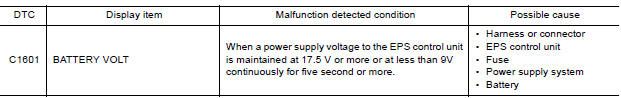
DTC CONFIRMATION PROCEDURE
1.PRECONDITIONING
If "DTC CONFIRMATION PROCEDURE" has been previously conducted, always turn ignition switch OFF and wait at least 10 seconds before conducting the next test.
>> GO TO 2.
2.DTC REPRODUCTION PROCEDURE
With CONSULT
- Turn the ignition switch OFF to ON.
- Perform "EPS" self-diagnosis.
Is DTC "C1601" detected?
YES >> Proceed to diagnosis procedure. Refer to STC "Diagnosis Procedure".
NO >> Inspection End.
Diagnosis Procedure
Regarding Wiring Diagram information, refer to STC "Wiring Diagram".
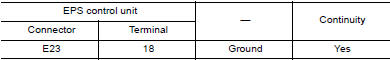
1.CHECK EPS CONTROL UNIT GROUND CIRCUIT
- Turn ignition switch OFF.
- Disconnect EPS control unit harness connector.
- Check continuity between EPS control unit harness connector terminal and
ground.
- Connect EPS control unit harness connector.
Is the inspection result normal?
YES >> GO TO 2.
NO >> Repair open circuit or short to ground or short to power in harness or connectors.
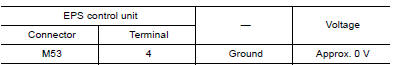
2.CHECK EPS CONTROL UNIT POWER SUPPLY CIRCUIT (1)
1. Check voltage between EPS control unit
harness connector terminal and ground.
2. Turn ignition switch ON.
CAUTION: Never start the engine.
3. Check voltage between EPS control unit
harness connector and ground. 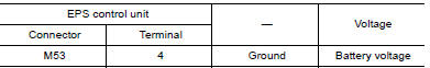
Is the inspection result normal?
YES >> GO TO 4.
NO >> GO TO 3.
3.CHECK EPS CONTROL UNIT POWER SUPPLY CIRCUIT (2)
- Turn ignition switch OFF.
- Check the 10A fuse (No. 5).
- Check the harness for open or short between EPS control unit harness connector M53 terminal 4 and the 10A fuse (No. 5).
Is the inspection result normal?
YES >> Perform the trouble diagnosis for ignition power supply circuit. Refer to PG "Wiring Diagram - Ignition Power Supply -".
NO >> Repair or replace malfunctioning component.
4.CHECK EPS CONTROL UNIT POWER SUPPLY CIRCUIT (3)
- Turn ignition switch OFF.
- Check voltage between EPS control unit harness connector terminal and
ground.
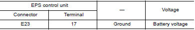
3. Turn ignition switch ON.
CAUTION: Never start the engine.
4. Check voltage between EPS control unit
harness connector and ground. 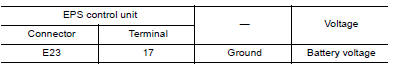
Is the inspection result normal?
YES >> GO TO 6.
NO >> GO TO 5.
5.CHECK EPS CONTROL UNIT POWER SUPPLY CIRCUIT (4)
- Turn ignition switch OFF.
- Check the 60A fusible link (J).
- Check the harness for open or short between EPS control unit harness connector E23 terminal 17 and the 60A fusible link (J).
Is the inspection result normal?
YES >> Perform the trouble diagnosis for power supply circuit. Refer to PG "Wiring Diagram - Battery Power Supply -".
NO >> Repair or replace malfunctioning component.
6.CHECK CONNECTOR
- Turn ignition switch OFF.
- Disconnect torque sensor harness connector.
- Check terminal for deformation, disconnection, looseness, and so on. If any malfunction is found, repair or replace terminal.
Is the inspection result normal?
YES >> Replace EPS control unit. Refer to STC "Removal and Installation".
NO >> Repair or replace malfunctioning component.
 Diagnosis and repair workflow
Other materials:
U0101 can comm circuit
Description
CAN (Controller Area Network) is a serial communication line for real time
application. It is an onvehicle multiplex
communication line with high data communication speed and excellent error
detection ability. Many electronic
control units are equipped onto a vehicle, and each con ...
P1715 Input speed sensor
Description
ECM receives input speed sensor signal from TCM via the CAN communication
line. ECM uses this signal for
engine control.
DTC Logic
DTC DETECTION LOGIC
NOTE:
If DTC P1715 is displayed with DTC UXXXX, first perform the
trouble diagnosis for DTC UXXXX.
If DTC P1715 is displa ...
Categories
- Manuals Home
- Nissan Versa Owners Manual
- Nissan Versa Service Manual
- Video Guides
- Questions & Answers
- External Resources
- Latest Updates
- Most Popular
- Sitemap
- Search the site
- Privacy Policy
- Contact Us

0.0049