Nissan Versa (N17): Diagnosis and repair workflow
Work Flow
DETAILED FLOW
1.INTERVIEW FROM THE CUSTOMER
Clarify customer complaints before inspection. First of all, perform an interview utilizing STC "Diagnostic Work Sheet" and reproduce symptoms to understand them fully. Ask customer about his/her complaints carefully.
Check symptoms by driving vehicle with customer, if necessary.
CAUTION: Customers are not professional. Never make assumptions like "maybe the customer means that...," or "maybe the customer mentioned this symptom".
>> GO TO 2.
2.CHECK SYMPTOM
Reproduce the symptom that is indicated by the customer, based on the information from the customer obtained by interview. Also check that the symptom is not caused by protection function. Refer to STC "Protection Function".
CAUTION: When the symptom is caused by normal operation, fully inspect each portion and obtain the understanding of customer that the symptom is not caused by a malfunction.
>> GO TO 3.
3.PERFORM SELF-DIAGNOSIS
With CONSULT
Perform self-diagnosis for "EPS".
Is any DTC detected?
YES >> Record or print self-diagnosis results. GO TO 4.
NO >> GO TO 6.
4.RECHECK SYMPTOM
With CONSULT
- Erase self-diagnostic results for "EPS".
- Perform DTC confirmation procedures for the malfunctioning system.
NOTE: If some DTCs are detected at the same time, determine the order for performing the diagnosis based on STC"DTC Inspection Priority Chart".
Is any DTC detected?
YES >> GO TO 5.
NO >> Check harness and connectors based on the information obtained by interview. Refer to GI "Intermittent Incident".
5.REPAIR OR REPLACE MALFUNCTIONING COMPONENT
- Repair or replace malfunctioning component.
- Reconnect part or connector after repairing or replacing.
- When DTC is detected, erase self-diagnostic results for "EPS".
>> GO TO 7.
6.IDENTIFY MALFUNCTIONING SYSTEM BY SYMPTOM DIAGNOSIS
Estimate malfunctioning system based on symptom diagnosis and perform inspection.
Can the malfunctioning system be identified?
YES >> GO TO 7.
NO >> Check harness and connectors based on the information obtained by interview. Refer to GI "Intermittent Incident".
7.FINAL CHECK
With CONSULT
- Check the reference value for EPS control unit.
- Recheck the symptom and check that symptom is not reproduced on the same conditions.
Is the symptom reproduced?
YES >> GO TO 3.
NO >> Inspection End.
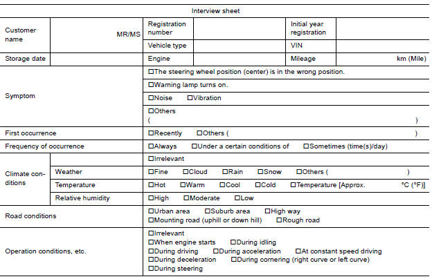
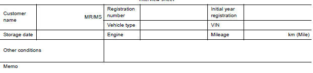
Diagnostic Work Sheet
Description
- In general, customers have their own criteria for a problem. Therefore, it is important to understand the symptom and status well enough by asking the customer about his/her concerns carefully. To systemize all the information for the diagnosis, prepare the interview sheet referring to the interview points.
- In some cases, multiple conditions that appear simultaneously may cause
a DTC to be detected.
Interview sheet sample
DTC/CIRCUIT DIAGNOSIS
 EPS control unit
Reference Value VALUES ON THE DIAGNOSIS TOOL CAUTION: The output signal indicates the EPS control unit calculation data. The normal values will be displayed even in the event that the output cir ...

Other materials:
Normal operating condition
Description
FUEL CUT CONTROL (AT NO LOAD AND HIGH ENGINE SPEED)
If the engine speed is above 2,400 rpm under no load (for example, the shift
lever position is neutral and
engine speed is over 2,400 rpm) fuel will be cut off after some time. The exact
time when the fuel is cut off varies
ba ...
Intelligent key system/engine start
function
INTELLIGENT KEY SYSTEM/ENGINE START
FUNCTION : System Description
SYSTEM DIAGRAM
SYSTEM DESCRIPTION
The engine start function of Intelligent Key system makes it possible to
start and stop the engine without
using the key, based on the electronic ID verification. The electronic ID
...
Categories
- Manuals Home
- Nissan Versa Owners Manual
- Nissan Versa Service Manual
- Video Guides
- Questions & Answers
- External Resources
- Latest Updates
- Most Popular
- Sitemap
- Search the site
- Privacy Policy
- Contact Us

0.0054