Nissan Versa (N17): B2621 Inside antenna
DTC Logic
DTC DETECTION LOGIC 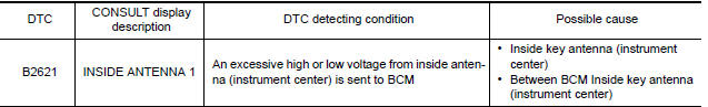
DTC CONFIRMATION PROCEDURE
1.PERFORM DTC CONFIRMATION PROCEDURE
- Select INTELLIGENT KEY of BCM using CONSULT.
- Select INSIDE ANT DIAGNOSIS in WORK SUPPORT mode.
- Perform inside key antenna (INSIDE ANT DIAGNOSIS) on WORK SUPPORT of INTELLIGENT KEY.
- Check BCM for DTC.
Is inside key antenna DTC detected?
YES >> Refer to DLK "Diagnosis Procedure".
NO >> Inside key antenna (instrument center) is OK.
Diagnosis Procedure
Regarding Wiring Diagram information, refer to DLK "INTELLIGENT KEY SYSTEM : Wiring Diagram".
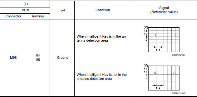
1.CHECK INSIDE KEY ANTENNA INPUT SIGNAL 1
- Turn ignition switch ON.
- Check signal between BCM harness connector and ground using
oscilloscope.
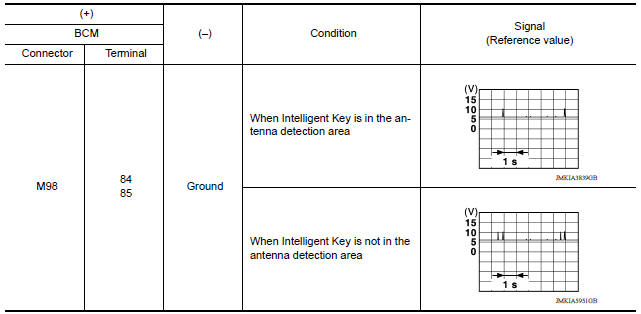
Is the inspection result normal?
YES >> Replace BCM. Refer to BCS"Removal and Installation".
NO >> GO TO 2.
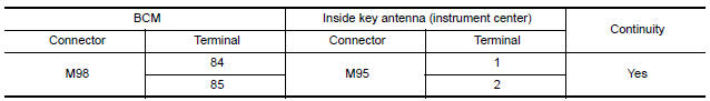
2.CHECK INSIDE KEY ANTENNA CIRCUIT
- Turn ignition switch OFF.
- Disconnect BCM connector and inside key antenna (instrument center) connector.
- Check continuity between BCM harness connector and inside key antenna
(instrument center) harness
connector.
- Check continuity between BCM harness connector and ground.
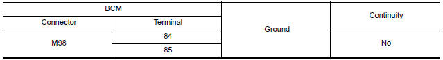
Is the inspection result normal?
YES >> GO TO 3.
NO >> Repair or replace harness.
3.CHECK INSIDE KEY ANTENNA INPUT SIGNAL 2
- Replace inside key antenna (instrument center). (New antenna or other antenna)
- Connect BCM connector and inside key antenna (instrument center) connector.
- Turn ignition switch ON.
- Check signal between BCM harness connector and ground using
oscilloscope.
Is the inspection result normal?
YES >> Replace inside key antenna (instrument center). Refer to DLK "INSTRUMENT CENTER : Removal and Installation".
NO >> Replace BCM. Refer to BCS "Removal and Installation".
 Inspection and adjustment
ADDITIONAL SERVICE WHEN REPLACING CONTROL UNIT (BCM) ...

Other materials:
Vehicle identification
Vehicle identification number (VIN) plate
The vehicle identification number (VIN) plate is
attached as shown. This number is the identification
for your vehicle and is used in the vehicle
registration.
Vehicle identification number (chassis number)
The vehicle identification number i ...
Road wheel
Inspection
ALUMINUM WHEEL
Check tires for wear and improper inflation.
Check wheels for deformation, cracks and other damage. If deformed,
remove wheel and check wheel
runout.
a. Remove tire from aluminum wheel and mount wheel on a balancer machine.
b. Set dial indicator as shown.
c ...
Categories
- Manuals Home
- Nissan Versa Owners Manual
- Nissan Versa Service Manual
- Video Guides
- Questions & Answers
- External Resources
- Latest Updates
- Most Popular
- Sitemap
- Search the site
- Privacy Policy
- Contact Us

0.0074