
Nissan Versa (N17): B2605 Shift position
DTC Logic
DTC DETECTION LOGIC
NOTE:
- If DTC B2605 is displayed with DTC U1000, first perform the trouble diagnosis for DTC U1000. Refer to BCS "DTC Logic".
- If DTC B2605 is displayed with DTC U1010, first perform the trouble
diagnosis for DTC U1010. Refer to
BCS "DTC Logic".
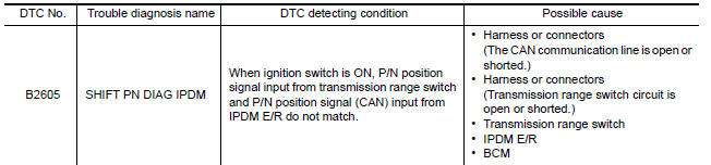
DTC CONFIRMATION PROCEDURE
1.PERFORM DTC CONFIRMATION PROCEDURE
1. Shift the selector lever to the P position.
2. Turn ignition switch ON and wait 1 second or more.
3. Shift the selector lever to the N position and wait 1 second or more.
4. Shift the selector lever to any position other than P and N, and wait 1 second or more.
5. Check DTC in Self Diagnostic Result mode of BCM using CONSULT.
Is DTC detected?
YES >> Go to SEC "Diagnosis Procedure".
NO >> Inspection End.
Diagnosis Procedure
Regarding Wiring Diagram information, refer to SEC "Wiring Diagram".
1.CHECK IPDM E/R INPUT SIGNAL
1. Turn ignition switch ON.
2. Check voltage between IPDM E/R harness connector and ground. 
Is the inspection result normal?
YES >> GO TO 3.
NO >> GO TO 2.
2.CHECK IPDM E/R INPUT SIGNAL CIRCUIT
1. Turn ignition switch OFF.
2. Disconnect IPDM E/R connector.
3. Disconnect transmission range switch connector.
4. Check continuity between IPDM E/R harness connector and transmission range
switch harness connector.
5. Check continuity between IPDM E/R harness connector and ground. 
Is the inspection result normal?
YES >> GO TO 5.
NO >> Repair or replace harness.
3.CHECK BCM INPUT SIGNAL
1. Check voltage between BCM harness connector and ground.
Is the inspection result normal?
YES >> GO TO 5.
NO >> GO TO 4.
4.CHECK BCM INPUT SIGNAL CIRCUIT
1. Turn ignition switch OFF.
2. Disconnect BCM connector.
3. Disconnect transmission range switch connector.
4. Check continuity between BCM harness connector and transmission range
switch harness connector.
5. Check continuity between IPDM E/R harness connector and ground. 
Is the inspection result normal?
YES >> GO TO 5.
NO >> Repair or replace harness.
5.REPLACE BCM
1. Replace BCM. Refer to BCS "Removal and Installation".
2. Perform initialization of BCM using CONSULT.
3. Perform DTC CONFIRMATION PROCEDURE for B2605. Refer to SEC "DTC Logic".
Is DTC B2605 detected again?
YES >> Replace IPDM E/R. Refer to PCS "Removal and Installation".
NO >> Inspection End.
 B2604 Shift position
Other materials:
Automatic speed control device (ASCD)
Automatic speed control device (ascd) : system diagram
NOTE:
Transmission range switch and TCM is also for A/T models.
Automatic speed control device (ascd) : system description
INPUT/OUTPUT SIGNAL CHART
Sensor
Input signal to ECM
ECM function
Actuator
Brake pedal ...
High-pressure pipe
Removal and Installation
CAUTION:
Perform oil return operation before each refrigeration system disassembly.
However, if a large amount
of refrigerant or oil is detected, do not perform oil return operation. Refer to
HA "Perform Oil
Return Operation".
REMOVAL
Remove low-press ...
Categories
- Manuals Home
- Nissan Versa Owners Manual
- Nissan Versa Service Manual
- Video Guides
- Questions & Answers
- External Resources
- Latest Updates
- Most Popular
- Sitemap
- Search the site
- Privacy Policy
- Contact Us

0.0071