Nissan Versa (N17): P1550 battery current sensor
DTC Logic
DTC DETECTION LOGIC
| DTC No. | Trouble diagnosis | DTC detecting condition | Possible cause |
| P1550 | Battery current sensor circuit range/performance | The output voltage of the battery current sensor remains within the specified range while engine is running. |
|
DTC CONFIRMATION PROCEDURE
1.PRECONDITIONING
If DTC Confirmation Procedure has been previously conducted, always perform the following procedure before conducting the next test.
- Turn ignition switch OFF and wait at least 10 seconds.
- Turn ignition switch ON.
- Turn ignition switch OFF and wait at least 10 seconds.
TESTING CONDITION: Before performing the following procedure, confirm that battery voltage is more than 8 V at idle.
>> GO TO 2.
2.PERFORM DTC CONFIRMATION PROCEDURE
- Start engine and wait at least 10 seconds.
- Check 1st trip DTC.
Is 1st trip DTC detected?
YES >> Go to EC, "Diagnosis Procedure".
NO >> INSPECTION END
Diagnosis Procedure
1.CHECK GROUND CONNECTION
- Turn ignition switch OFF.
- Check ground connection E. Refer to Ground Inspection in GI, "Circuit Inspection".
Is the inspection result normal?
YES >> GO TO 2.
NO >> Repair or replace ground connection.
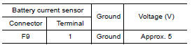
2.CHECK BATTERY CURRENT SENSOR POWER SUPPLY
- Disconnect battery current sensor harness connector.
- Turn ignition switch ON.
- Check the voltage between battery current sensor harness connector and
ground.
Is the inspection result normal?
YES >> GO TO 4.
NO >> GO TO 3.
3.CHECK BATTERY CURRENT SENSOR POWER SUPPLY CIRCUIT
- Turn ignition switch OFF.
- Disconnect ECM harness connector.
- Check the continuity between battery current sensor harness connector
and ECM harness connector.
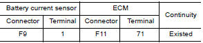
- Also check harness for short to ground and short to power.
Is the inspection result normal?
YES >> Check intermittent incident. Refer to GI, "Intermittent Incident".
NO >> Repair or replace error-detected parts.
4.CHECK BATTERY CURRENT SENSOR GROUND CIRCUIT FOR OPEN AND SHORT
- Turn ignition switch OFF.
- Disconnect ECM harness connector.
- Check the continuity between battery current sensor harness connector
and ECM harness connector.
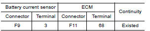
- Also check harness for short to ground and short to power.
Is the inspection result normal?
YES >> GO TO 5.
NO >> Repair or replace error-detected parts.
5.CHECK BATTERY CURRENT SENSOR INPUT SIGNAL CIRCUIT FOR OPEN AND SHORT
- Check the continuity between battery current sensor harness connector
and ECM harness connector.
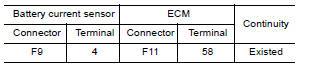
- Also check harness for short to ground and short to power.
Is the inspection result normal?
YES >> GO TO 6.
NO >> Repair or replace error-detected parts.
6.CHECK BATTERY CURRENT SENSOR
Check battery current sensor. Refer to EC, "Component Inspection".
Is the inspection result normal?
YES >> Check intermittent incident. Refer to GI, "Intermittent Incident".
NO >> Replace battery negative cable assembly.
Component Inspection
1.CHECK BATTERY CURRENT SENSOR
- Turn ignition switch OFF.
- Reconnect harness connectors disconnected.
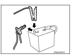
- Disconnect battery negative cable (1).
- Install jumper cable (A) between battery negative terminal and
body ground.
 : To body
ground.
: To body
ground. - Turn ignition switch ON.
- Check the voltage between ECM harness connector terminals
as per the following.
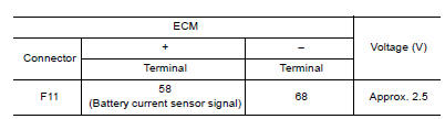 Before measuring the
terminal voltage, confirm that the battery is fully charged. Refer to PG,
"How to Handle Battery".
Before measuring the
terminal voltage, confirm that the battery is fully charged. Refer to PG,
"How to Handle Battery".
Is the inspection result normal?
YES >> INSPECTION END
NO >> Replace battery negative cable assembly.
 P1226 TP sensor
Other materials:
Positive crankcase ventilation
Inspection
1.CHECK PCV VALVE
With engine running at idle, remove PCV valve from rocker cover. A
properly working valve makes a hissing noise as air passes through
it. A strong vacuum should be felt immediately when a finger is
placed over valve inlet.
Is the inspection result normal?
YES &g ...
Automatic door lock/unlock function
AUTOMATIC DOOR LOCK/UNLOCK FUNCTION
: System Diagram
AUTOMATIC DOOR LOCK/UNLOCK FUNCTION
: System Description
DOOR LOCK FUNCTION
The door lock and unlock switch (driver side) is built into power window
main switch.
The door lock and unlock switch (passenger side) is on door trim. ...
Categories
- Manuals Home
- Nissan Versa Owners Manual
- Nissan Versa Service Manual
- Video Guides
- Questions & Answers
- External Resources
- Latest Updates
- Most Popular
- Sitemap
- Search the site
- Privacy Policy
- Contact Us

0.006