Nissan Versa (N17): Engine control system symptoms
Symptom Table
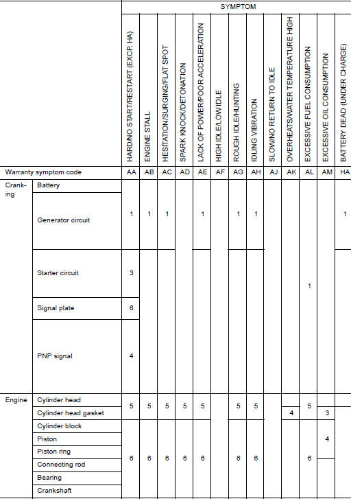
SYSTEM - BASIC ENGINE CONTROL SYSTEM
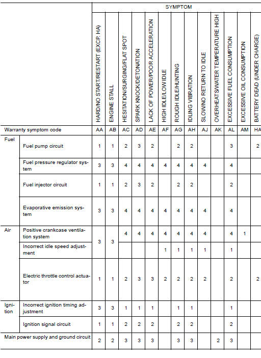
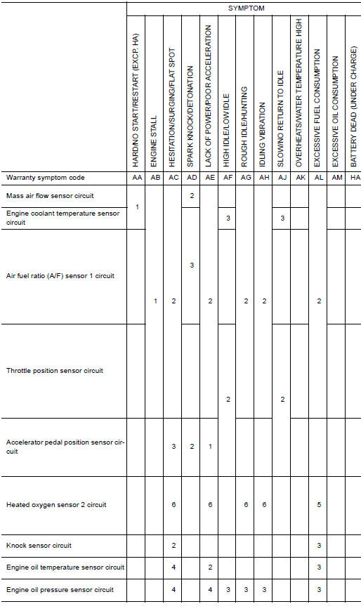
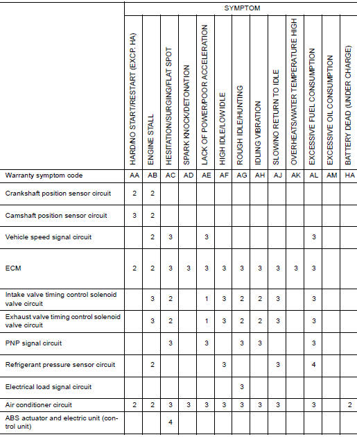
1 - 6: The numbers refer to the order of inspection.
(continued on next table)
SYSTEM - ENGINE MECHANICAL & OTHER
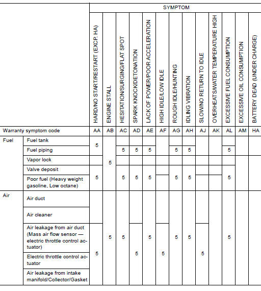
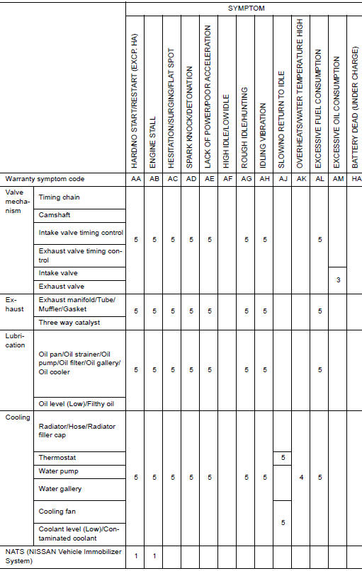
1 - 6: The numbers refer to the order of inspection.
 Refrigerant pressure sensor
Normal operating condition
Description FUEL CUT CONTROL (AT NO LOAD AND HIGH ENGINE SPEED) If the engine speed is above 2,400 rpm under no load (for example, the shift lever position is neutral and engine speed is over 2 ...
Other materials:
Brake pedal
Inspection and Adjustment
INSPECTION
Brake Pedal Height
Check the height (H1) between the dash lower panel (1) and the
brake pedal upper surface.
(H1) : Refer to BR "Brake Pedal".
CAUTION:
Remove the floor trim.
Stop Lamp Switch
Check the clearance (C) among the brake ped ...
Preparation
Special Service Tool
The actual shape of Kent-Moore tools may differ from those of special service
tools illustrated here.
HFC-134a (R-134a) Service Tool and Equipment
Do not mix HFC-134a (R-134a) refrigerant and/or its specified oil with CFC-12
(R-12) refrigerant and/or its oil.
Separ ...
Categories
- Manuals Home
- Nissan Versa Owners Manual
- Nissan Versa Service Manual
- Video Guides
- Questions & Answers
- External Resources
- Latest Updates
- Most Popular
- Sitemap
- Search the site
- Privacy Policy
- Contact Us

0.0051