Nissan Versa (N17): Evaporator
Removal and Installation
REMOVAL
- Remove A/C unit assembly. Refer to HA "Removal and Installation".
- Disassemble A/C unit assembly and the evaporator assembly.
- Remove thermo control amp. from evaporator assembly.
CAUTION: If reusing the evaporator, mark the location of the thermo control amp. for installation.
- Remove bolts and the evaporator.
INSTALLATION
Installation is in the reverse order of removal.
CAUTION:
- Do not reuse O-rings.
- Apply A/C oil to the new O-rings for installation.
- When installing the intake sensor (automatic air conditioner) or the thermo control amp. (manual air conditioner), place in the same position as before replacement.
- Do not rotate the bracket insertion part when removing and installing the intake sensor (automatic air conditioner) or the thermo control amp. (manual air conditioner).
- Perform oil adjusting procedure after installing new evaporator. Refer to HA "Oil Adjusting Procedure for Components Replacement Except Compressor".
- After charging the A/C refrigerant, check for leaks. Refer to HA "Leak Test".
UNIT DISASSEMBLY AND ASSEMBLY
A/C UNIT ASSEMBLY
Exploded View
UNIT DISASSEMBLY
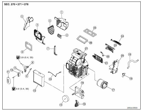
1. Rear intake case 2. Sub intake door 3. Intake door 4. Front intake case 5. Foot duct (RH) 6. Packing 7. Filter cover 8. Evaporator pipe assembly 9. O-ring 10. Expansion valve 11. Grommet 12. Evaporator 13. Intake sensor 14. Packing 15. Heater pipe flange 16. Heater core 17. Blower motor 18. Aspirator 19. Aspirator hose 20. Foot duct (LH) 21. Air mix door 22. Center plate 23. Foot door 24. Ventilator door 25. Packing 26. Packing 27. A/C unit case assembly
SERVICE DATA AND SPECIFICATIONS (SDS)
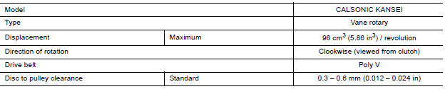
Compressor
Oil
|
Application |
HR16DE | |
| Type | NISSAN A/C System Oil Type R (DH-PR) | |
| Capacity | Total in system | 120 m (4.1 US fl oz, 4.2 lmp fl oz) |
| Compressor (service part) charging | Refer to HA "Description". | |
Refrigerant 
 A/C Unit assembly
Exploded View 1. Cap 2. Steering member 3. Cap 4. Bracket 5. A/C unit assembly Pawl Removal and Installation CAUTION: Perform oil return operation before each refrigeration system disassemb ...

Other materials:
Control panel buttons - color screen with Navigation System (if so equipped)
WARNING
Positioning of the heating or air conditioning
controls and display controls
should not be done while driving in order
that full attention may be given to
the driving operation.
Do not disassemble or modify this system.
If you do, it may result in accidents,
fire, or elec ...
Water outlet
Exploded View
M/T models
1. Engine coolant temperature sensor 2. Clamp 3. Gasket
4. Clamp 5. Bracket 6. Clamp
7. Water outlet 8. Clamp 9. Clamp
10. Cylinder block heater (Canada) A. From electric throttle control actuator B.
To radiator
C. From heater core D. To heater core E. To electric ...
Categories
- Manuals Home
- Nissan Versa Owners Manual
- Nissan Versa Service Manual
- Video Guides
- Questions & Answers
- External Resources
- Latest Updates
- Most Popular
- Sitemap
- Search the site
- Privacy Policy
- Contact Us

0.0046