Nissan Versa (N17): A/C Unit assembly
Exploded View
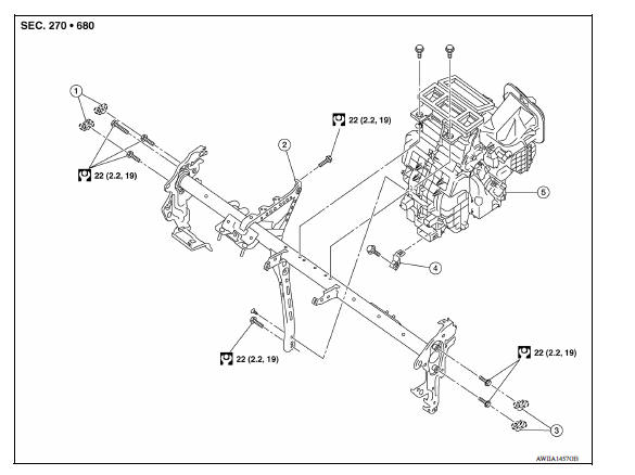
1. Cap 2. Steering member 3. Cap
4. Bracket 5. A/C unit assembly  Pawl
Pawl
Removal and Installation
CAUTION: Perform oil return operation before each refrigeration system disassembly. However, if a large amount of refrigerant or oil is detected, do not perform oil return operation. Refer to HA "Perform Oil Return Operation".
NOTE: When removing components such as hoses, tubes/lines, etc., cap or plug openings to prevent fluid from spilling.
REMOVAL
- Use refrigerant collecting equipment (for HFC-134a) to discharge the refrigerant. Refer to HA "Recycle Refrigerant".
- Drain engine coolant from cooling system. Refer to CO"Draining Engine Coolant".
- Remove low-pressure flexible hose and high-pressure pipe. Refer to HA
"Removal and Installation"
and HA "Removal and Installation" (if equipped).
CAUTION: Cap or wrap the joint of the A/C piping and expansion valve with suitable material such as vinyl tape to avoid the entry of air.
- Remove clamps and disconnect heater hoses from A/C unit assembly (if equipped).
- Remove the instrument panel assembly. Refer to IP "Removal and Installation".
- Disconnect drain hose from A/C unit assembly.
- Disconnect the necessary harness connectors and clips required to remove the steering member. Position the vehicle harness as necessary.
- Remove the BCM screws.
- Remove the J/B screws.
- Remove ground bolts.
- Remove the bolts, steering member and A/C unit assembly.
- Remove bolts and A/C unit assembly from the steering member.
INSTALLATION
Installation is in the reverse order of removal.
CAUTION:
- Do not reuse O-rings.
- Apply A/C oil to the O-rings of the low-pressure flexible hose and high pressure flexible pipe for installation.
- After charging the refrigerant, check for leaks. Refer to HA "Leak Test".
NOTE: Refer to CO "Refilling Engine Coolant" when filling radiator with engine coolant.
 Refrigerant pressure sensor
Removal and Installation CAUTION: Perform oil return operation before each refrigeration system disassembly. However, if a large amount of refrigerant or oil is detected, do not perform oil retu ...
Evaporator
Removal and Installation REMOVAL Remove A/C unit assembly. Refer to HA "Removal and Installation". Disassemble A/C unit assembly and the evaporator assembly. Remove thermo control a ...
Other materials:
Power steering
WARNING
If the engine is not running or is turned
off while driving, the power assist for
the steering will not work. Steering will
be harder to operate.
When the power steering warning light
illuminates with the engine running,
there will be no power assist for the
steering. You w ...
Wheel alignment
Inspection
DESCRIPTION
CAUTION:
The adjustment mechanisms of camber and toe-in are not included.
If camber and toe-in is outside the standard, check front
suspension parts for wear and damage.
Replace suspect parts if a malfunction is detected.
Measure wheel alignment under unladen ...
Categories
- Manuals Home
- Nissan Versa Owners Manual
- Nissan Versa Service Manual
- Video Guides
- Questions & Answers
- External Resources
- Latest Updates
- Most Popular
- Sitemap
- Search the site
- Privacy Policy
- Contact Us

0.0048