Nissan Versa (N17): Front door speaker
Diagnosis Procedure
Regarding Wiring Diagram information, refer to AV "Wiring Diagram".
1.CONNECTOR CHECK
Check the audio unit and speaker connectors for the following:
- Proper connection.
- Damage.
- Disconnected or loose terminals.
Is the inspection result normal?
YES >> GO TO 2.
NO >> Repair the terminals and connectors.
2.CHECK FRONT DOOR SPEAKER SIGNAL CIRCUIT CONTINUITY
1. Disconnect audio unit connector M43 and suspect front door speaker connector.
2. Check continuity between audio unit connector M43 and suspect front door
speaker connector.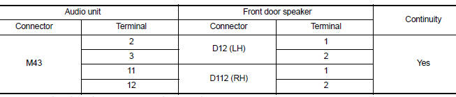
3. Check continuity between audio unit connector M43 and ground.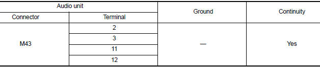
Is the inspection result normal?
YES >> GO TO 3
NO >> Repair harness or connector.
3.CHECK FRONT DOOR SPEAKER SIGNAL
1. Connect audio unit connector M43 and suspect front door speaker connector.
2. Turn ignition switch to ACC.
3. Push audio unit POWER switch.
4. Check signal between terminals of audio unit connector M43. 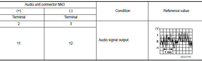
Is the inspection result normal?
YES >> Replace front door speaker. Refer to AV "Removal and Installation".
NO >> Replace audio unit. Refer to AV "Removal and Installation".
 Power supply and ground circuit
AUDIO UNIT AUDIO UNIT : Diagnosis Procedure Regarding Wiring Diagram information, refer to AV "Wiring Diagram". 1.CHECK FUSES Check that the following fuses are not blown. & ...
Rear door speaker
Diagnosis Procedure Regarding Wiring Diagram information, refer to AV "Wiring Diagram". 1.CONNECTOR CHECK Check the audio unit and speaker connectors for the following: Proper connect ...
Other materials:
U0140 Lost communication (BCM)
DTC Logic
DTC DETECTION LOGIC
DTC
Trouble diagnosis name
DTC detection condition
Possible causes
U0140
Lost Communication With Body
Control Module
When the ignition switch is ON,
TCM is unable to receive the
CAN communications signal
from BCM continuously ...
P0711 Transmission fluid temperature
sensor A
DTC Logic
DTC DETECTION LOGIC
DTC
Trouble diagnosis name
DTC detection condition
Possible causes
P0711
Transmission Fluid Temperature
Sensor "A" Circuit Range/
Performance
Under the following diagnosis
conditions, A/T fluid temperature
does not rise to ...
Categories
- Manuals Home
- Nissan Versa Owners Manual
- Nissan Versa Service Manual
- Video Guides
- Questions & Answers
- External Resources
- Latest Updates
- Most Popular
- Sitemap
- Search the site
- Privacy Policy
- Contact Us

0.006