Nissan Versa (N17): Power supply and ground circuit
AUDIO UNIT
AUDIO UNIT : Diagnosis Procedure
Regarding Wiring Diagram information, refer to AV "Wiring Diagram".
1.CHECK FUSES
Check that the following fuses are not blown. 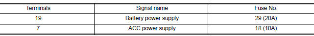
Are the fuses blown?
YES >> Replace the blown fuse after repairing the affected circuit.
NO >> GO TO 2.
2.POWER SUPPLY CIRCUIT CHECK
1. Turn ignition switch OFF.
2. Disconnect audio unit connector M43.
3. Check voltage between audio unit connector M43 and ground. 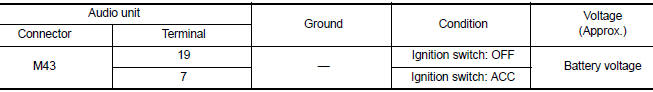
Is the inspection result normal?
YES >> GO TO 3.
NO >> Repair or replace harness or connectors.
3.GROUND CIRCUIT CHECK
Inspect audio unit case ground.
Is the inspection result normal?
YES >> Inspection End.
NO >> Repair audio unit case ground.
 Diagnosis and repair workflow
Work Flow OVERALL SEQUENCE DETAILED FLOW 1.GET INFORMATION FOR SYMPTOM Get detailed information from the customer about the symptom (the condition and the environment when the incident/ma ...
Front door speaker
Diagnosis Procedure Regarding Wiring Diagram information, refer to AV "Wiring Diagram". 1.CONNECTOR CHECK Check the audio unit and speaker connectors for the following: Proper conne ...
Other materials:
Diagnosis and repair work flow
Work Flow
OVERALL SEQUENCE
*1 SRC "Diagnosis Description" *2 SRC "SRS Operation Check" *3 SRC
"Trouble Diagnosis with
CONSULT" *4 SRC "Trouble Diagnosis without CONSULT"
DETAILED WORK FLOW
1.CUSTOMER INFORMATION
Get detailed information from the c ...
Refrigeration system
Refrigerant Cycle
REFRIGERANT FLOW
The refrigerant flows in the standard pattern, that is, through the
compressor, the condenser with liquid tank,
through the evaporator, and back to the compressor. The refrigerant evaporation
through the evaporator coils
are controlled by externally equaliz ...
Categories
- Manuals Home
- Nissan Versa Owners Manual
- Nissan Versa Service Manual
- Video Guides
- Questions & Answers
- External Resources
- Latest Updates
- Most Popular
- Sitemap
- Search the site
- Privacy Policy
- Contact Us

0.0053