Nissan Versa (N17): Front drive shaft
Exploded View
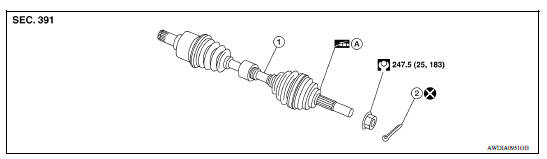
1. Drive shaft 2. Cotter pin A. Apply Molykote M77
Removal and Installation
REMOVAL
- Remove the wheel and tire assembly using power tool. Refer to WT "Adjustment".
- Remove wheel sensor and sensor harness. Refer to BRC "FRONT WHEEL SENSOR : Removal and Installation".
- Remove brake lock plate from strut assembly.
- Remove brake caliper using power tool, leaving brake caliper hydraulic
lines connected. Reposition brake
caliper aside with wire. Refer to BR "BRAKE CALIPER ASSEMBLY : Exploded
View".
NOTE: Avoid depressing brake pedal while brake caliper is removed.
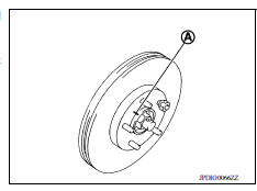
- Put matching marks (A) on disc rotor and wheel hub and bearing assembly, then remove disc rotor.
CAUTION:
- Put matching marks (A) on the wheel hub and the disc rotor before removing the disc rotor.
- Do not drop disc rotor.
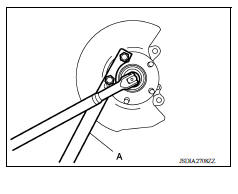
6. Remove and discard cotter pin, and then loosen wheel hub lock nut, using Tool (A).
Tool number : KV40104000 ( - )
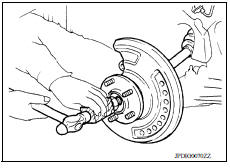
- Separate the drive shaft from the wheel hub and bearing assembly by lightly tapping the end of the drive shaft using a suitable tool and a wood block.
CAUTION:
- Do not place drive shaft joint at an extreme angle. Also be careful not to overextend slide joint.
- Do not allow drive shaft to hang down without support for joint sub-assembly, shaft and the other parts.
NOTE: Use suitable puller, if wheel hub and drive shaft cannot be separated even after performing the above procedure.
- Remove wheel hub lock nut.
- Remove the nuts and bolts, then separate the steering knuckle from strut assembly. Refer to FSU"Removal and Installation".
- Remove drive shaft from wheel hub.
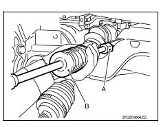
- Use the Tool (A) and a suitable tool (B) while inserting tip of the drive shaft attachment between shaft and transaxle assembly, and then remove drive shaft from transaxle assembly.
Tool number : KV40107500 ( - )
CAUTION:
- Do not place drive shaft joint at an extreme angle when removing drive shaft. Also be careful not to overextend slide joint.
- Confirm that the circular clip is attached to the drive shaft.
INSTALLATION
Installation is in the reverse order of removal.
Transaxle Side
- Always replace differential side oil seal with new one when installing drive shaft. Refer to TM "Removal and Installation".
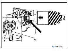
- Place the protector (A) onto transaxle assembly to prevent damage to the oil seal while inserting drive shaft. Slide drive shaft sliding joint and tap with a hammer to install securely.
Tool number : KV38107900 ( - )
CAUTION: Check that circular clip is completely engaged.
Wheel Hub Side
CAUTION:
- During the installation, do not damage the wheel bearing seal. If damage has occurred, replace wheel bearing with a new one.
- Do not allow paint to adhere to the wheel bearing seal.
- Check each mating surface for water and foreign matter. If there is any water or foreign matter, clean the mating surface.
- Clean the mating surface of wheel hub lock nut and wheel hub.
CAUTION: Do not apply lubricating oil to the mating surface of the wheel hub lock nut and the wheel hub.
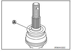
- Clean the mating surface of drive shaft, wheel hub, and wheel bearing. And then apply Molykote M77 to surface (A) of joint subassembly of drive shaft.
CAUTION: Apply Molykote M77 to cover entire flat surface of joint subassembly of drive shaft.
Molykote M77 quantity : 1.0 - 3.0 g (0.04 - 0.10 oz)
-
Perform the final tightening of each of parts under unladen conditions, which were removed when removing wheel hub and axle housing.
-
When installing a cotter pin, securely bend the end portion to prevent rattles.
CAUTION: Do not reuse cotter pin.
UNIT DISASSEMBLY AND ASSEMBLY
 Front wheel hub and knuckle
Exploded View 1. Steering knuckle 2. Splash guard 3. Wheel bearing 4. Snap ring 5. Wheel stud 6. Wheel hub 7. Disc rotor 8. Cotter pin A. Apply Molykote M77 ...
Front drive shaft
Exploded View 1. Circlip 2. Dust shield 3. Slide joint housing 4. Snap ring 5. Spider assembly 6. Boot band 7. Boot 8. Shaft 9. Damper band 10. Dynamic damper 11. Circlip 12. Joint sub-assemb ...
Other materials:
Consult function
APPLICATION ITEMS
Diagnostic test mode
Function
Work Support
This mode enables a technician to adjust some devices faster and
more accurately.
Self Diagnostic Results
Retrieve DTC from ECU and display diagnostic items.
Data Monitor
Monitor the input ...
P2859 Clutch A pressure
DTC Logic
DTC DETECTION LOGIC
DTC
Trouble diagnosis name
DTC detection condition
Possible causes
P2859
Clutch A pressuren disengagement
performance
The detection conditions continuously for 200
msec or more under the following diagnosis
conditions:- Diagnosi ...
Categories
- Manuals Home
- Nissan Versa Owners Manual
- Nissan Versa Service Manual
- Video Guides
- Questions & Answers
- External Resources
- Latest Updates
- Most Popular
- Sitemap
- Search the site
- Privacy Policy
- Contact Us

0.005