Nissan Versa (N17): Fuel level sensor unit
Disassembly and Assembly
Fuel Level Sender Unit
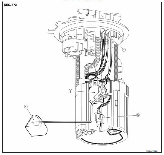
1. Harness connectors 2. Level sending unit module 3. Fuel temperature sensor 4. Float arm assembly
Disassembly
NOTE: Before disassembly, note the proper placement of the wires to the correct terminals and correct wire routing to the terminals.
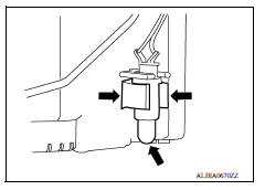
- Disconnect the red, white, and double black wire connectors.
- Press the tabs on the terminals to release the locking tabs.
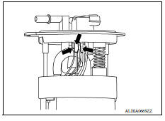
2. Release the two clips and remove the fuel temperature sensor from the pump assembly.
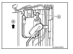
3. Release the tab (A) and slide the level sending unit module and float arm assembly up (B) to remove.
Assembly
Assembly is in the reverse order of disassembly.
NOTE:
- Ensure proper placement of the wires to the correct terminals and correct wire routing to the terminals.
- After connecting terminals, ensure they are securely locked and can not be pulled out.
- When installing the level sending unit, push down until the tab is locked into place.
SERVICE DATA AND SPECIFICATIONS (SDS)
Fuel Tank
STANDARD AND LIMIT
| Fuel tank capacity | Approx. 41.0  (10-7/8 US
gal, 9 Imp gal) (10-7/8 US
gal, 9 Imp gal) |
| Fuel recommendation | Refer to GI, "Fuel (Regular Unleaded Gasoline Recommended) HR16DE". |
 EVAP control system pressure sensor
Exploded View 1. EVAP control system pressure sensor 2. O-ring 3. EVAP canister Removal and Installation NOTE: The EVAP canister system pressure sensor can be removed without removing the E ...
Precautions
Precaution for Supplemental Restraint System (SRS) "AIR BAG" and "SEAT BELT PRE-TENSIONER" The Supplemental Restraint System such as "AIR BAG" and "SEAT BELT PRE-TENSIONER", us ...
Other materials:
Spark plugs
Replacing spark plugs
Platinum-tipped spark plugs
It is not necessary to replace platinum-tipped A
spark plugs as frequently as conventional type
spark plugs because they last much longer. Follow
the maintenance log shown in the Maintenance
and Schedules section of this manual. Do
not ser ...
Intake valve timing control
Intake valve timing control : System Diagram
Intake valve timing control : system description
INPUT/OUTPUT SIGNAL CHART
Sensor
Input signal to ECM
ECM function
Actuator
Crankshaft position sensor (POS)
Engine speed*1
Piston position
Intake valve timing
con ...
Categories
- Manuals Home
- Nissan Versa Owners Manual
- Nissan Versa Service Manual
- Video Guides
- Questions & Answers
- External Resources
- Latest Updates
- Most Popular
- Sitemap
- Search the site
- Privacy Policy
- Contact Us

0.0046