
Nissan Versa (N17): Input shaft and gear
Exploded View
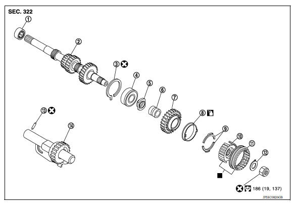
1. Input shaft front bearing 2. Input shaft 3. Snap ring
4. Input shaft rear bearing 5. Adapter plate 6. Bushing
7. 5th input gear 8. 5th-reverse baulk ring 9. Synchronizer lever
10. 5th-reverse synchronizer hub 11. 5th-reverse coupling sleeve 12. Lock washer
13. Retaining pin 14. Reverse gear  :
Apply gear oil.
:
Apply gear oil.  : Replace the parts
as a set.
: Replace the parts
as a set.
Disassembly
Refer to TM, "Disassembly" for disassembly procedure.
Assembly
Refer to TM, "Assembly" for assembly procedure.
Inspection
INSPECTION AFTER DISASSEMBLY
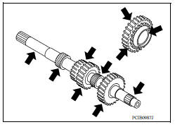
Input Shaft and Gear
Check the following items and replace if necessary.
- Damage, peeling, uneven wear, and distortion of shaft.
- Excessive wear, damage, and peeling of gear.
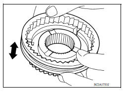
Synchronizer
Check for the following and replace if necessary.
- Contact surface breakage, damage, and unusual wear of coupling sleeve, synchronizer hub, and synchronizer lever.
- Coupling sleeve and synchronizer hub move smoothly.
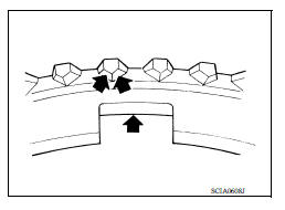
- Breakage, damage, and excessive wear of baulk ring cam surface and synchronizer lever contact surface.
Bearing
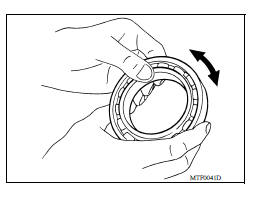
Check bearing for damage and rough rotation. Replace if necessary.
 Transaxle assembly
Mainshaft and gear
Exploded View 1. Mainshaft front bearing 2. Mainshaft 3. 1st main gear 4. 1st inner baulk ring 5. 1st synchronizer cone 6. 1st outer baulk ring 7. 1st-2nd synchronizer hub 8. 1st-2nd coupling ...
Other materials:
Continuously Variable Transmission (CVT) fluid (if so equipped)
CAUTION
NISSAN recommends using Genuine
NISSAN CVT Fluid NS-3 (or equivalent)
ONLY in NISSAN CVTs. Do not mix with
other fluids.
Do not use Automatic transmission
fluid (ATF) or Manual transmission fluid
in a NISSAN CVT, as it may damage the
CVT. Damage caused by the use of fluids
...
Diagnosis and repair workflow
Work Flow
OVERALL SEQUENCE
DETAILED FLOW
1.INTERVIEW FOR MALFUNCTION
Find out what the customer's concerns are.
>> GO TO 2.
2.SYMPTOM CHECK
Verify the symptom from the customer's information.
>> GO TO 3.
3.BASIC INSPECTION
Check the operation of each part. Check any concer ...
Categories
- Manuals Home
- Nissan Versa Owners Manual
- Nissan Versa Service Manual
- Video Guides
- Questions & Answers
- External Resources
- Latest Updates
- Most Popular
- Sitemap
- Search the site
- Privacy Policy
- Contact Us

0.0102