Nissan Versa (N17): Camshaft
Exploded View
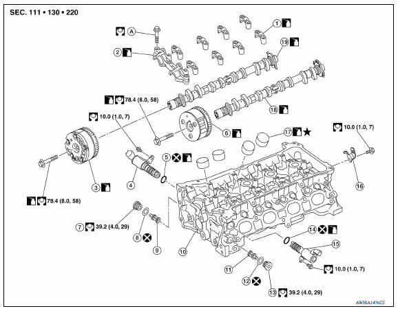
1. Camshaft bracket (No. 2 to 5) 2. Camshaft bracket (No. 1) 3. Camshaft sprocket (EXH) 4. Exhaust valve timing control solenoid valve 5. Oring 6. Camshaft sprocket (INT) 7. Plug (EXH) 8. Washer (EXH) 9. Oil filter (for exhaust valve timing control solenoid valve) 10. Cylinder head 11. Oil filter (for intake valve timing control solenoid valve) 12. Washer (INT) 13. Plug (INT) 14. Oring 15. Intake valve timing control solenoid valve 16. Bracket 17. Valve lifter 18. Camshaft (INT) 19. Camshaft (EXH)
Removal and Installation
CAUTION:
The rotation direction indicated in the procedure is as viewed from the engine front.
REMOVAL
- Hold the bottom surface of the engine with a jack to remove the right engine mount assembly and the insulator.
- Remove rocker cover.
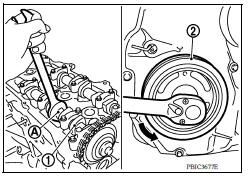
- Place cylinder No. 1 at TDC of its compression stroke:
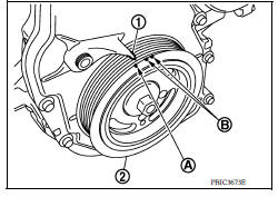
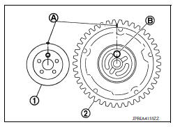
a. Rotate crankshaft pulley (2) clockwise and align TDC mark (without paint mark) (A) to timing indicator (1) on front cover.
(B) : White paint mark (Not used for service)
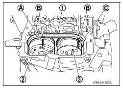
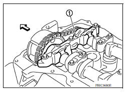
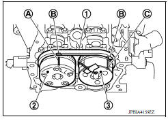
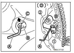
b. Check that the matching marks on each of the camshaft sprockets are in the position as shown.
(1) : Timing chain
(2) : Camshaft sprocket (EXH)
(3) : Camshaft sprocket (INT)
(A) : Matching mark (Peripheral groove)
(B) : Pink link
(C) : Matching mark (Peripheral groove)
- If not, rotate crankshaft pulley one more turn to align matching marks to the positions as shown.
c. Paint matching marks (A) on the timing chain links.
- Remove crankshaft pulley.
- Remove front cover.
- Secure the plunger of chain tensioner in the fully compressed position. Then, loosen the timing chain tension.
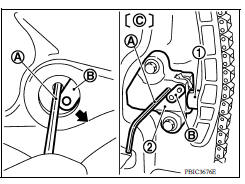
a. Fully push down the lever (B) of chain tensioner (2) from the plug hole, and then insert the stopper pin (A) into the body side hole and secure the lever at the lowest position.
(C) : Front cover has been removed for clarity.
- The tab is released by fully pushing the lever down. As a result, the plunger (1) can be moved.
NOTE:
Hexagonal wrench [2.5 mm (0.098 in)] is used for a stopper pin as an example.
CAUTION:
The stopper pin must use a shape that cannot fall in the front cover if dropped.
b. Turn the crankshaft pulley (2) counterclockwise with the camshaft (EXH) (1) held. Apply the tension to the timing chain, and then push the plunger into the inside of chain tensioner.
CAUTION:
Hold the camshaft hexagonal part (A), and then secure the camshaft.
c. Pull out the stopper pin (A) of chain tensioner (2) side from plug hole. Lift the lever (B) up to align its hole position with the hole of the body.
(D) : Front cover has been removed for clarity.
- When the lever hole (C) is aligned with the body hole position, the plunger (1) is secured.
- When the protrusion parts of the plunger ratchet and the tab face each other, both hole positions are not aligned. At that time, correctly engage them and align these hole positions by slightly moving the plunger.
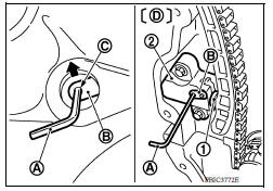
d. Insert the stopper pin into the body hole through the lever hole, and then secure the lever at the upper position.
- Remove timing chain.
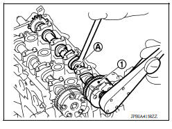
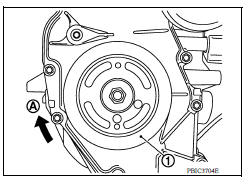
- Remove camshaft sprocket (EXH) (1).
CAUTION:
- Hold the camshaft hexagonal part (A), and then secure the camshaft.
- Do not rotate crankshaft and camshaft separately, so as not to contact valve with piston.
NOTE:
The timing chain with the front cover installed is not disengaged from the crankshaft sprocket and it is not dropped into the front cover. Therefore, the timing chain tension holding device is not necessary.
9. Turn the camshaft sprocket (INT) to the most advanced position.
CAUTION:
Installation and removal of the camshaft sprocket (INT) must be done in the most advanced position.
Make sure to follow the procedure exactly.
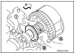
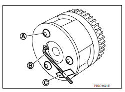
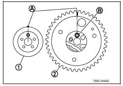
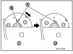
- The sprocket (C) and vane (camshaft coupling) (B) are designed to spin and move within the range of a certain angle.
- With the engine stopped and the vane in the most retarded angle, it will not spin because it is locked to the sprocket side by the internal lock pin (A).
- If the camshaft sprocket bolts are turned in the situation described above, the lock pin will become damaged and cause malfunctions because of the increased horizontal load (cutting force) on the lock pin.
- Put the camshaft sprocket (INT) in the most advanced position:
a. Remove camshaft bracket (No. 1) (1).
 : Engine front
- Loosen the bolts in several steps, and then remove them.
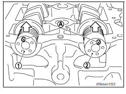
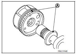
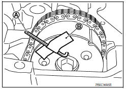
b. Apply the following air pressure to the No. 1 journal oil hole (A) of camshaft (INT) (1) shown using an air gun.
Air pressure : 300 kPa (3.1 kg/cm2, 44 psi) or more
- Apply the air pressure into the oil hole on the second groove from the front of camshaft thrust (B).
- Proceed all the way through step "e" with the air pressure on.
- Attach the rubber nozzle narrowed to the top of the air gun to prevent air leakage from the oil hole (A). Securely apply the air pressure to the oil hole.
WARNING:
Eye protection should be worn as needed.
CAUTION:
- There are other oil holes in the side grooves. Do not use the incorrect oil holes.
- Be sure not to damage the oil path with the tip of the air gun.
- Wipe all the oil off the air gun to prevent oil from being blown all over along with the air, and the area around the air gun should be wiped with a rag when applying air pressure. Eye protection should be worn as needed.
NOTE:
The air pressure is used to move the lock pin into the disengage position.
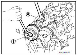
c. Hold the camshaft sprocket (INT) with hands, and then apply the power counterclockwise/clockwise alternately.
(A) : Air gun
(B) : Rubber nozzle
- Finally rotate the sprocket of the camshaft sprocket (INT)
counterclockwise [the direction shown by the arrow (
 )].
)]. - Perform the work while continuously applying the air pressure to the oil hole.
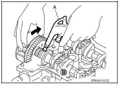
- If the lock pin is not released, tap the camshaft sprocket (INT) lightly with a plastic hammer (A).
- If the camshaft sprocket (INT) is not rotated counterclockwise even if the above procedures are performed, check the air pressure and the oil hole position.
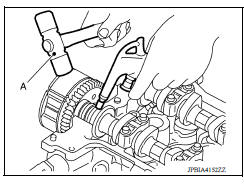
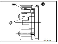
d. While doing the above, once you hear a click (the sound of the internal lock pin disengaging) from inside the camshaft sprocket (INT), start turning the camshaft sprocket (INT) in the counterclockwise direction in the most advanced angle position.
(C) : Lock pin engaged
(D) : Most advanced angle
- Keep the air pressure on.
- If there is no click, as soon as the vane side (camshaft side) starts moving independently of the sprocket, the lock pin has become disengaged.
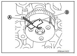
- Check that it is in the most advanced angle position by seeing if the stopper pin groove (A) and the stopper pin hole (B) are matched up as shown.
e. Stop applying air pressure and release the camshaft (INT).
f. Insert the stopper pin (A) into the stopper pin holes in the camshaft sprocket (INT) and lock in the most advanced angle position.
CAUTION:
No load is exerted on the stopper pin (spring reaction, etc.).
Since it comes out easily, secure it with tape (B) to prevent it from falling out.
NOTE:
The stopper pin shows one example of a hexagonal wrench for 2.5 mm (0.098 in) [length of inserted section: approximately15 mm (0.59 in)].
10. Remove the camshaft sprocket (INT):
a. Keeping the camshaft hexagonal part (A) in place with the wrench, loosen the bolts for the camshaft sprocket (INT) (2).
(1) Camshaft (INT)
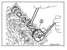
CAUTION:
- Do not drop stopper pin.
- Tape (C) the stopper pin (B) so it does not come out.
- Do not subject it to impact by dropping.
- Do not disassemble. [Do not loosen the three bolts (A)].
NOTE:
While removing the camshaft sprocket (INT), if you have taken out the stopper pin and the lock pin has been rejoined in the most retarded angle, do the following to restore it.
i. Install the camshaft (INT) and tighten the bolts enough to prevent air from leaking out.
CAUTION:
The internal lock pin will get damaged, so keep the torque on the bolts to the minimum required to prevent air from escaping.
ii. Apply the air pressure, disengage the lock pin, and turn the vane to the most advanced angle position.
iii. Insert the stopper pin.
iv. Remove camshaft sprocket (INT) from the camshaft.
11. Remove camshaft brackets (No. 2 to 5).
- Loosen bolts in several steps in the reverse order as shown.
(A) : EXH side
(B) : INT side
 : Engine front
NOTE:
The camshaft bracket (No. 1) has been already removed.
- Remove camshaft (EXH).
- Remove camshaft (INT).
- Remove valve lifter.
- Identify installation positions, and store lifters without mixing them up.
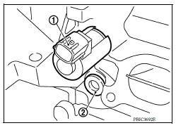
- Remove intake valve timing control solenoid valve (1).
- Remove the alternator and bracket, remove the plug (2), and then remove the oil filter
- Remove exhaust valve timing control solenoid valve.
- Remove the plug on the exhaust valve timing control solenoid valve and the oil filter.
- For component inspection after removal
INSTALLATION
CAUTION:
Do not reuse Orings or washers.
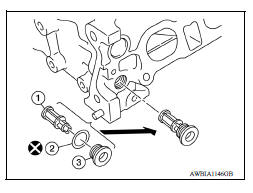
1. Install oil filter (1) for intake and exhaust valve timing control solenoid valves.
CAUTION:
Do not reuse washers.
NOTE:
The intake side is shown as an example.
- The oil filter (1) and washer (2) are assembled to the plug (3), and then install them in to the cylinder head.
2. Install intake and exhaust valve timing control solenoid valves.
- Insert it straight into the cylinder head.
- Tighten bolts.
3. Install valve lifters.
- If they are reused, install them in the original positions.
4. Put a matching mark for positioning the camshaft (INT) and the camshaft sprocket (INT):
NOTE:
This helps prevent the knock pin from engaging with the incorrect pin hole after installing the camshaft (INT) and the camshaft sprocket (INT).
a. Put the matching marks (A) on a line extending from the knock pin position of camshaft (INT) (1) front surface.
- Put the marks on the visible position with the camshaft sprocket installed as shown.
b. Put the matching marks on a line extending from the knock pin hole (B) position of camshaft sprocket (INT) (2) as shown.
- Put the marks on the visible position with it installed to the camshaft.
5. Put a matching mark for positioning the camshaft (EXH) and the camshaft sprocket (EXH):
NOTE:
This helps prevent the knock pin from engaging with the incorrect pin hole after installing the camshaft (INT) and the camshaft sprocket (EXH).
a. Put the matching marks (A) on a line extending from the knock pin position of camshaft (EXH) (1) front surface.
- Put the marks on the visible position with the camshaft sprocket installed as shown.
b. Put the matching marks on a line extending from the knock pin hole (B) position of camshaft sprocket (EXH) (2) as shown.
- Put the marks on the visible position with it installed to the camshaft.
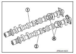
6. Install camshaft
(1) : Camshaft (EXH)
(2) : Camshaft (INT)
(A) : Identification mark
- Note that the camshafts (INT and EXH) have different shapes at the rear.
- Install camshafts to the cylinder head so that knock pins (A) on front end are positioned as shown.
(1) : Camshaft (EXH)
(2) : Camshaft (INT)
 : Upper side
NOTE:
Though camshaft does not stop at the portion as shown for the placement of cam nose, it is generally accepted camshaft is placed for the same direction as shown.
7. Install camshaft brackets (No. 2 to 5) aligning the identification marks on upper surface as shown.
(A) : EXH side
(B) : INT side
: Engine front
- Install so that identification mark can be correctly read when viewed from the INT side.
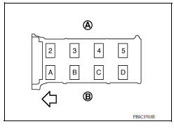
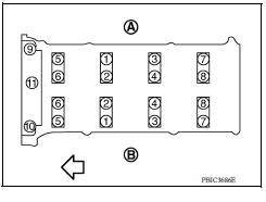
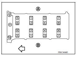
8. Tighten bolts of camshaft brackets in the following steps, in numerical order as shown.
(A) : EXH side
(B) : INT side
: Engine front
a. Tighten No. 9 to 11 in numerical order.
Camshaft bracket bolts : 1.96 N*m (2.0 kgm, 14 inlb)
b. Tighten No. 1 to 8 in numerical order.
Camshaft bracket bolts : 1.96 N*m (2.0 kgm, 14 inlb)
c. Tighten all bolts in numerical order.
Camshaft bracket bolts : 5.88 N*m (0.60 kgm, 52 inlb)
d. Tighten all bolts in numerical order.
Camshaft bracket bolts : 10.4 N*m (1.1 kgm, 8 ftlb)
9. Install the camshaft sprocket (INT and EXH) to the camshaft (INT and EXH):
a. Refer to the matching mark (A) added in step 4. Securely align the knock pin and the pin hole, and then install them.
NOTE:
The intake side is shown as an example.
10. Tighten the camshaft sprocket bolt (INT and EXH).
(1) : Camshaft sprocket (EXH)
CAUTION:
Hold the camshaft hexagonal part (A), using a suitable tool to secure the camshaft.
11. Install the camshaft (INT and EXH) to the camshaft sprocket (INT and EXH) (2 and 3) while aligning the matching mark (marked when timing chain is removed) (A) and the pink link (B) of camshaft sprocket (INT and EXH).
(1) : Timing chain
(C) : Matching mark (peripheral groove)
- If the positions of knock pin and pin groove are not aligned, move the camshaft (EXH) slightly to correct these positions.
12. Pull out the stopper pin (A), and then apply the tension to the timing chain by rotating the crankshaft pulley clockwise slightly.
(1) : Plunger
(2) : Chain tensioner
(B) : Lever
(C) : Lever hole
(D) : Front cover has been removed for clarity.
- Pull out the stopper pin of chain tensioner.
- Install front cover.
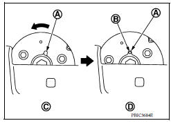
- Return the camshaft sprocket (INT) in the most retarded position:
a. Remove the stopper pin (A) from the camshaft sprocket (INT).
(B) : Tape
b. Turn the crankshaft pulley (1) slowly clockwise (A) and return the camshaft sprocket (INT) to the most retarded angle position.
- When first turning the crankshaft, the camshaft sprocket (INT) will turn. Once it is turned more, and the vane (camshaft) also turns, then it has reached the most retarded angle position.
(B) : Stopper pin hole
(C) : Most advanced angle
(D) : Lock pin engaged
- The most retarded angle position can be checked by seeing if the stopper pin groove (A) is shifted clockwise.
- After spinning the crankshaft slightly in the counterclockwise direction, you can check the lock pin has joined by seeing if the vane (camshaft) and the sprocket move together.
16. Install the camshaft position sensor (PHASE) to the rear end of cylinder head.
- Tighten bolts with it completely inserted.
17. Check and adjust valve clearance.
18. Installation of the remaining components is in the reverse order of removal.
INSPECTION AFTER INSTALLATION
- Before starting engine, check oil/fluid levels, including engine coolant and engine oil. If less than required quantity, fill to the specified level.
- Use procedure below to check for fuel leakage.
- Turn ignition switch ON (with engine stopped). With fuel pressure applied to fuel piping, check for fuel leakage at connection points.
- Start engine. With engine speed increased, check again for fuel leakage at connection points.
- Run engine to check for unusual noise and vibration.
NOTE:
If hydraulic pressure inside timing chain tensioner drops after removal and installation, slack in the guide may generate a pounding noise during and just after engine start. However, this is normal. Noise will stop after hydraulic pressure rises.
- Warm up engine thoroughly to make sure there is no leakage of fuel, exhaust gas, or any oils/fluids including engine oil and engine coolant.
- Bleed air from passages in lines and hoses, such as in cooling system.
- After cooling down engine, again check oil/fluid levels including engine oil and engine coolant. Refill to specified level, if necessary.
- Summary of the inspection items:
| Item | Before starting engine | Engine running | After engine stopped | |
| Engine coolant | Level | Leakage | Level | |
| Engine oil | Level | Leakage | Level | |
| Transmission/ transaxle fluid | A/T and CVT Models | Leakage | Level/Leakage | Leakage |
| M/T Models | Level/Leakage | Leakage | Level/Leakage | |
| Other oils and fluids* | Level | Leakage | Level | |
| Fuel | Leakage | Leakage | Leakage | |
| Exhaust gas | Leakage | |||
*Power steering fluid, brake fluid, etc.
Inspection
INSPECTION AFTER REMOVAL
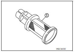
Oil Filter
- Check that there is no foreign material on the oil filter (1) and check it for clogging.
- Check the oil filter for damage.
- If there is some damage, replace the oil filter, the plug, and the washer as a set.
CAUTION:
Do not reuse the washer.
Camshaft Runout
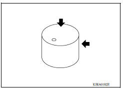
1. Put Vblock on a precise flat table, and support No. 2 and 5 journals of camshaft.
CAUTION:
Do not support No. 1 journal (on the side of camshaft sprocket) because it has a different diameter from the other four locations.
- Set a dial indicator vertically to No. 3 journal.
- Turn camshaft to one direction, and measure the camshaft runout on the dial indicator. (Total indicator reading)
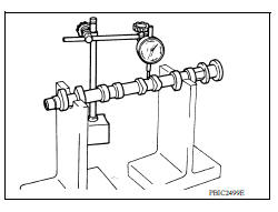
4. If it exceeds the limit, replace camshaft.
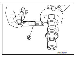
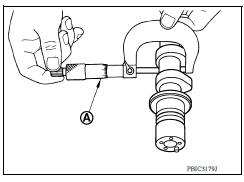
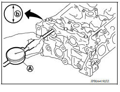
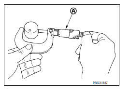
Camshaft Cam Height
1. Measure the camshaft cam height with a micrometer (A).
2. If wear exceeds the limit, replace camshaft.
Camshaft Journal Oil Clearance
CAMSHAFT JOURNAL DIAMETER
Measure the outer diameter of camshaft journal with a micrometer (A).
CAMSHAFT BRACKET INNER DIAMETER
- Tighten camshaft bracket bolts to the specified torque. Refer to "INSTALLATION" for the tightening procedure.
- Measure inner diameter (b) of camshaft bracket with a bore gauge (A).
CAMSHAFT JOURNAL OIL CLEARANCE
- (Oil clearance) = (Camshaft bracket inner diameter) - (Camshaft journal diameter)
- If it exceeds the limit, replace either or both camshaft and cylinder head.
NOTE:
Camshaft brackets cannot be replaced as single parts, because they are machined together with cylinder head. Replace whole cylinder head assembly.
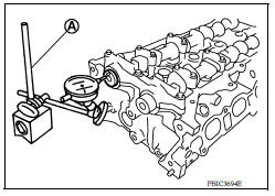
Camshaft End Play
- Install camshaft in cylinder head.
- Install a dial indicator (A) in thrust direction on front end of
camshaft.
Measure the camshaft end play on the dial indicator when camshaft is moved forward/backward (in direction to axis).
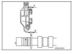
- Measure the following parts if out of the standard.
- Dimension "A" for cylinder head No. 1 journal bearing
Standard : 4.000 4.030 mm (0.1574 0.1586 in)
- Dimension "B" for camshaft thrust
Standard : 3.877 3.925 mm (0.1526 0.1545 in)
- Refer to the standards above, and then replace camshaft and/ or cylinder head.
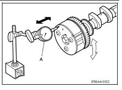
Camshaft Sprocket Runout
1. Put Vblock on precise flat table, and support No. 2 and 5 journals of camshaft.
CAUTION:
Do not support No. 1 journal (on the side of camshaft sprocket) because it has a different diameter from the other four locations.
2. Measure the camshaft sprocket runout with a dial indicator (A).
(Total indicator reading)
Limit : 0.15 mm (0.0059 in)
- If it exceeds the limit, replace camshaft sprocket.
Valve Lifter
Check if surface of valve lifter has any wear or cracks.
- If anything above is found, replace valve lifter.
Valve Lifter Clearance
VALVE LIFTER OUTER DIAMETER
- Measure the outer diameter of valve lifter with a micrometer (A).
VALVE LIFTER HOLE DIAMETER
Measure the diameter of valve lifter hole of cylinder head with an inside micrometer (A).
VALVE LIFTER CLEARANCE
- (Valve lifter clearance) = (Valve lifter hole diameter) - (Valve lifter outer diameter)
- If out of the standard, referring to the each standard of valve lifter outer diameter and valve lifter hole diameter, replace either or both valve lifter and cylinder head.
INSPECTION AFTER INSTALLATION
Inspection of Camshaft Sprocket Oil Groove
CAUTION:
- Perform this inspection only when DTC P0011 or P0014 is detected in selfdiagnostic results of CONSULT and it is directed according to inspection procedure of EC section.
- Check when engine is cold so as to prevent burns from the splashing engine oil.
NOTE:
This section provides the inspection method of oil passage of cam sprocket on the intake side. For oil passage on the exhaust side, the inspection procedure must be changed as instructed below:
Step 3 : Remove exhaust valve timing control solenoid valve. Refer to EM56, "Exploded View".
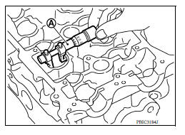
Step 4 : Crank engine, and then check that engine oil comes out from exhaust valve timing control solenoid valve hole (A). End crank after checking.
Step 5 Perform the following inspection if engine oil does not come out from exhaust valve timing control solenoid valve oil hole of the cylinder head.
- Remove oil filter, and then clean it. Refer to EM56, "Exploded View".
- Clean oil groove between oil strainer and exhaust valve timing control solenoid valve. Refer to EM56, "Exploded View".
Step 6 : Remove components between exhaust valve timing control solenoid valve and camshaft sprocket (EXH), and then check each oil groove for clogging.
- Check engine oil level.
- Perform the following procedure so as to prevent the engine from being unintentionally started while checking.
a. Release the fuel pressure.
b. Remove intake manifold.
c. Disconnect ignition coil and injector harness connectors.
- Remove intake valve timing control solenoid valve.
- Crank engine, and then check that engine oil comes out from intake valve timing control solenoid valve hole (A). End crank after checking.
(1) : Plug
 :Engine front
WARNING:
- Be careful not to touch rotating parts (drive belts, idler pulley, and crankshaft pulley, etc.).
CAUTION:
- Prevent splashing by using a shop cloth to prevent injury from splashing engine oil and so as to prevent engine oil contamination.
- Use a shop cloth to prevent engine oil from being splashed to engine and vehicle. Especially be careful not to spill engine oil to rubber parts of drive belts, engine mounting insulator, etc. Wipe engine oil off immediately if it is splashed.
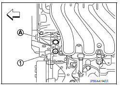
5. Perform the following inspection if engine oil does not come out from intake valve timing control solenoid valve oil hole of the cylinder head.
- Remove oil filter, and then clean it.
- Clean oil groove between oil strainer and intake valve timing control solenoid valve.
6. Remove components between intake valve timing control solenoid valve and camshaft sprocket (INT), and then check each oil groove for clogging.
- Clean oil groove if necessary.
7. After inspection, installation of components is in the reverse order of removal
 Timing chain
Exploded View 1. Timing chain slack guide 2. Timing chain tensioner 3. Camshaft sprocket (EXH) 4. Camshaft sprocket (INT) 5. Plug 6. Front oil seal 7. Crankshaft pulley 8. Crankshaft pulley b ...
Valve oil seal
VALVE OIL SEAL : Removal and Installation REMOVAL Remove camshafts. Remove valve lifters. Rotate crankshaft, and set piston with valve oil seal to be removed to TDC. This will prevent ...
Other materials:
Final drive
Exploded View
1. Differential side bearing outer race 2. Differential side bearing 3. Final
drive
: Replace the parts as a set.
Disassembly
Remove differential side bearings, using Tool (A) and suitable tool.
Tool number : ST33052000 ( - )
Assembly
Install differential sid ...
P072D Stuck in 2GR
DTC Logic
DTC DETECTION LOGIC
DTC
Trouble diagnosis name
DTC detection condition
Possible causes
P072D
Stuck in Gear 2
The following diagnosis conditions
are met and the detection
conditions continue for 0.5 seconds
or more.- Diagnosis condition
- Shiftin ...
Categories
- Manuals Home
- Nissan Versa Owners Manual
- Nissan Versa Service Manual
- Video Guides
- Questions & Answers
- External Resources
- Latest Updates
- Most Popular
- Sitemap
- Search the site
- Privacy Policy
- Contact Us

0.0073