Nissan Versa (N17): Brake booster and check valve
Exploded View
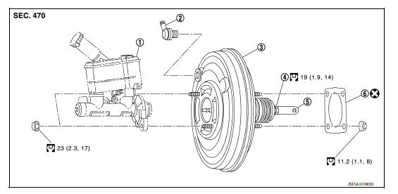
1. Master cylinder assembly 2. Check valve 3. Brake booster 4. Lock nut 5. Clevis 6. Gasket
Removal and installation
REMOVAL
NOTE: When removing components such as hoses, tubes/lines, etc., cap or plug openings to prevent fluid from spilling.
- Remove brake master cylinder assembly. Refer to BR "Removal and Installation".
- Remove vacuum hose from check valve. Refer to BR "Removal and Installation".
- Remove and discard the clip (1) and clevis pin (2). Refer to BR "Exploded View".
- Remove nuts on brake booster and brake pedal assembly. Refer to BR "Exploded View".
- Remove brake booster from dash panel on engine room side.
CAUTION: Do not deform or bend the brake tubes.
NOTE: If removing brake booster is difficult, remove clevis from brake booster.
- Remove check valve from brake booster.
- Perform inspection after removal. Refer to BR "Inspection and Adjustment".
INSTALLATION
CAUTION: Do not spill or splash brake fluid on painted surfaces. Brake fluid may seriously damage paint. Wipe it off immediately and wash with water if it gets on a painted surface.
Note the following, and install in the reverse order of removal.
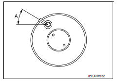
- Set check valve angle (A) as shown.
(A) : 45
- Be careful not to damage brake booster stud bolt threads. If brake booster is tilted during installation, the dash panel may damage the threads.
- Do not deform or bend the brake tubes when installing the brake booster.
- Always use a new gasket between the brake booster and the dash panel.
- Replace the clevis pin and clip during installation. Refer to BR "Inspection and Adjustment".
- Do not allow foreign matter (e.g. dust) and oils other than brake fluid to enter the reservoir tank.
- After installation, perform the air bleeding. Refer to BR "Bleeding
Brake System".
CAUTION: Do not reuse drained brake fluid.
- Check each item of brake pedal. Adjust it if the measurement value is not the standard. Refer to BR "Inspection and Adjustment".
Inspection and Adjustment
INSPECTION BEFORE REMOVAL
Brake System Vacuum Inspection
CAUTION: Check the vacuum condition when the master cylinder and the brake booster are installed.
- Check the vacuum using a suitable tool.
At vacuum of −66.7 kPa (−500 mmHg, −19.69 inHg) : Vacuum should decrease within 3.3 kPa (24.8 mmHg, 0.98 inHg) for 15 seconds.
2. If the vacuum cannot be maintained, perform the following operation.
a. Check that dirt and dust are not present on the brake booster and brake master cylinder mating surfaces.
Clean the mating surfaces if necessary.
b. Check the O-ring on the master cylinder. If anything is found, replace the O-ring. Refer to BR "Removal and Installation".
c. Check the vacuum condition again. If the condition still cannot be maintained, replace the brake booster.
INSPECTION AFTER REMOVAL
Check Valve Vacuum Inspection
- Check the vacuum using a suitable tool.
When connected to the booster side : Vacuum should decrease within 1.3 kPa (9.8 mmHg, 0.38 inHg) for 15 seconds under a vacuum of −66.7 kPa (−500 mmHg, − 19.69 inHg).
When connected to the vacuum hose side :Vacuum should not exist.
2. If the vacuum still cannot be maintained, replace the check valve.
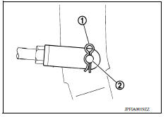
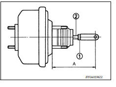
Input Rod Length Inspection
- Loosen the lock nut (1) and adjust the input rod (2) to the specified length (A).
(A) : Refer to BR "Brake Booster".
2. Tighten the lock nut to the specified torque.
INSPECTION AFTER INSTALLATION
Operation
Depress the brake pedal several times at 5-second intervals with the engine stopped. Start the engine with the brake pedal fully depressed. Check that the clearance between brake pedal and dash lower pane decreases.
NOTE: A slight impact with a small click may be felt on the pedal when the brake pedal is fully depressed. This is a normal phenomenon due to the brake system operation.
Air Tight
- Run the engine at idle for 1 minute to apply vacuum to the brake booster, and stop the engine. Then depress the brake pedal several times at 5-second intervals until the accumulated vacuum is released to atmospheric pressure. Check that the clearance between brake pedal and dash lower panel gradually increases each time the brake pedal is depressed when performing this operation.
- Depress the brake pedal with the engine running. Then stop the engine while holding down the brake pedal. Check that the brake pedal stroke does not change after holding down the brake pedal for 30 seconds or more.
ADJUSTMENT AFTER INSTALLATION
Perform the brake pedal adjustment after installing the brake pedal assembly. Refer to BR"Inspection and Adjustment".
 Brake master cylinder
Exploded View 1. Reservoir cap 2. Brake fluid strainer 3. Reservoir tank 4. Grommet 5. Cylinder body 6. Brake fluid level switch 7. O-ring Apply brake fluid PBC (Poly Butyl Cuprysil) grease or ...
Vacuum lines
Exploded View 1. Clamp 2. Vacuum hose 3. Vacuum piping A. To brake booster B. Paint mark C. To intake manifold Removal and Installation REMOVAL Remove the air cleaner and duct assembly. ...
Other materials:
Water outlet
Exploded View
M/T models
1. Engine coolant temperature sensor 2. Clamp 3. Gasket
4. Clamp 5. Bracket 6. Clamp
7. Water outlet 8. Clamp 9. Clamp
10. Cylinder block heater (Canada) A. From electric throttle control actuator B.
To radiator
C. From heater core D. To heater core E. To electric ...
Clutch master cylinder
Exploded View
1. Reservoir hose 2. Master cylinder
Removal and Installation
CAUTION:
Do not spill clutch fluid onto painted surfaces. If fluid spills,
wipe up immediately and wash the
affected area with water.
Do not disassemble clutch master cylinder.
NOTE:
When removing compo ...
Categories
- Manuals Home
- Nissan Versa Owners Manual
- Nissan Versa Service Manual
- Video Guides
- Questions & Answers
- External Resources
- Latest Updates
- Most Popular
- Sitemap
- Search the site
- Privacy Policy
- Contact Us

0.0059