Nissan Versa (N17): Brake master cylinder
Exploded View
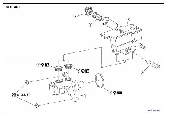
1. Reservoir cap 2. Brake fluid strainer 3. Reservoir tank
4. Grommet 5. Cylinder body 6. Brake fluid level switch
7. O-ring  Apply brake fluid
 PBC (Poly Butyl Cuprysil) grease or
silicone-based grease
PBC (Poly Butyl Cuprysil) grease or
silicone-based grease
Removal and Installation
CAUTION:
- Be careful not to splash brake fluid on painted areas; it may cause paint damage. If brake fluid is splashed on painted areas, wash it away with water immediately.
- Do not scratch the piston of master cylinder when installing/removing because the piston is exposed. Check for any dust on the piston, and wash with brake fluid if needed.
- Hold the master cylinder body when handing the master cylinder assembly. Do not hold the piston because the piston might become detached if pulled strongly.
- Refill the reservoir tank with new brake fluid "DOT 3".
- Do not reuse drained brake fluid.
- Do not reuse master cylinder O-ring.
NOTE: When removing components such as hoses, tubes/lines, etc., cap or plug openings to prevent fluid from spilling.
REMOVAL
- Drain brake fluid. Refer to BR "Draining".
- Remove battery. Refer to PG "Removal and Installation".
- Remove air duct and air cleaner case. Refer to EM "Removal and Installation".
- Position the IPDM E/R aside to obtain access to the master cylinder. Refer to PCS "Removal and Installation".
- Disconnect the harness connector from the brake fluid level switch.
- Disconnect the brake pipe from the master cylinder assembly with a flare
nut wrench.
CAUTION: Do not scratch the flare nut and the brake tube.
- Remove the master cylinder assembly.
CAUTION:
- Do not deform or bend the brake pipes.
- Do not depress the brake pedal after the master cylinder assembly is removed.
- The piston of the master cylinder assembly is exposed. Do not damage it when removing the master cylinder.
- The piston may drop off when pulled out strongly. Do not hold the piston. Hold the cylinder body when handling the master cylinder assembly.
8. Remove and discard the O-ring.
INSTALLATION
CAUTION:
- Do not spill or splash brake fluid on painted surfaces. Brake fluid may seriously damage paint. Wipe it off immediately and wash with water if it gets on a painted surface.
- Do not reuse the O-ring.
Note the following, and install in the reverse order of removal.
- Do not depress the brake pedal after the master cylinder assembly is removed.
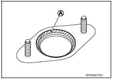
- Apply silicone grease to the brake booster location (A) prior to installing the master cylinder assembly to the brake booster.
- The piston of the master cylinder assembly is exposed. Do not damage it when handling the master cylinder and check that no dirt and dust are present on the piston before installation. Clean it with new brake fluid if necessary.
- The piston may drop off when pulled strongly. Do not hold the piston.
Hold the cylinder body when handling the master cylinder assembly.
- Do not deform or bend the brake pipes.
- Temporarily tighten the brake tube flare nut to the master cylinder
assembly by hand. Then tighten it to the specified torque with a
flare nut torque wrench. Refer to BR "FRONT : Exploded View".
CAUTION: Do not scratch the flare nut and the brake tube.
- Do not allow foreign matter (e.g. dust) and oils other than brake fluid to enter the reservoir tank.
- After installation, perform the air bleeding. Refer to BR "Bleeding Brake System" CAUTION: Do not reuse drained brake fluid.
- Perform inspection after installation. Refer to BR "Inspection".
Disassembly and Assembly
DISASSEMBLY
CAUTION:
- Do not disassemble the cylinder body.
- Remove the reservoir tank only when necessary.
- Do not drop the removed parts. The parts must not be reused if they are dropped.
Remove the reservoir tank and grommet from the cylinder body.
ASSEMBLY
CAUTION:
- Do not use mineral oils such as kerosene or gasoline and rubber grease during the cleaning and assembly process.
- Do not drop the when installing. The parts must not be reused if they are dropped.
- Do not allow foreign matter (e.g. dust) and oils other than brake fluid to enter the reservoir tank.
- Apply new brake fluid to the grommet and install it to the cylinder
body.
CAUTION: Do not reuse the grommets.
- Install the reservoir tank to the cylinder body.
Inspection
INSPECTION AFTER INSTALLATION
- Check the following items and replace if necessary.
- Check the master cylinder for deformation, twist, contact with other parts or looseness of connection.
- Check for fluid leakage from connection. Refer to BR, "FRONT :
Inspection".
CAUTION: If the fluid leakage is present, retighten to the specified torque. Replace if necessary.
 Rear
Rear
REAR : Exploded View 1. Rear brake pipe assembly (RH) 2. Rear brake pipe assembly (LH) 3. Lock plate 4. Rear brake hose 5. Wheel cylinder brake pipe assembly A. To rear brake hose B. To brak ...
Brake booster and check valve
Exploded View 1. Master cylinder assembly 2. Check valve 3. Brake booster 4. Lock nut 5. Clevis 6. Gasket ...
Other materials:
Brake and clutch (if so equipped) fluid
For additional information on brake fluid specification,
refer to "Recommended fluids/lubricants
and capacities" in the "Technical and consumer
information" section of this manual.
WARNING
Use only new fluid from a sealed container.
Old, inferior or contaminated
fluid may damage the br ...
Vehicle identification
Vehicle identification number (VIN) plate
The vehicle identification number (VIN) plate is
attached as shown. This number is the identification
for your vehicle and is used in the vehicle
registration.
Vehicle identification number (chassis number)
The vehicle identification number i ...
Categories
- Manuals Home
- Nissan Versa Owners Manual
- Nissan Versa Service Manual
- Video Guides
- Questions & Answers
- External Resources
- Latest Updates
- Most Popular
- Sitemap
- Search the site
- Privacy Policy
- Contact Us

0.0053