Nissan Versa (N17): Instrument panel assembly
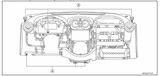
Exploded View
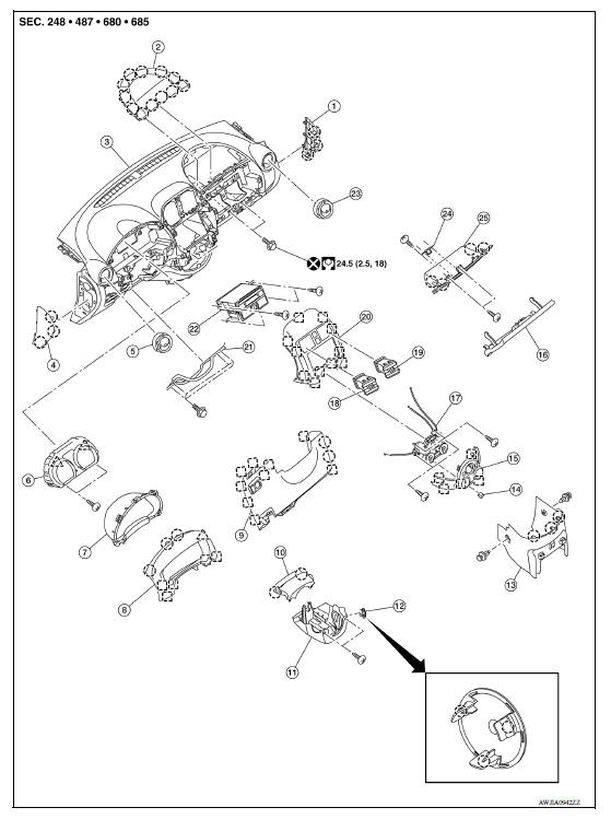
1. Instrument side finisher (RH) 2. Passenger air bag module 3. Instrument
panel assembly
4. Instrument side finisher (LH) 5. Ventilator grilles (LH) 6. Combination meter
7. Combination meter finisher 8. Cluster lid A 9. Instrument lower panel LH
10. Steering column upper cover 11. Steering column lower cover 12. Steering
lock escutcheon
13. Center console lower 14. Control knob 15. A/C control finisher
16. Glove box lid 17. A/C control 18. Ventilator grilles center (LH)
19. Ventilator grilles center (RH) 20. Cluster lid C 21. Lower knee protector (LH)
22. Audio unit or AV control unit (if
equipped)
23. Ventilator grilles (RH) 24. Glove box striker
25. Glove box  Metal clip
 Clip
Clip
 Pawl
Pawl
Removal and Installation
CAUTION:
- Disconnect both the negative and positive battery terminals, then wait at least three minutes.
- Do not tamper with or force air bag lid open, as this may adversely affect air bag performance.
- To prevent damage to the parts, when removing, always use a suitable tool that is made of plastic.
- Be careful not to scratch instrument panel pad or other parts.
REMOVAL
- Disconnect the negative and positive battery terminals, then wait at least three minutes. Refer to PG "Removal and Installation".
- Remove front pillar finishers (LH/RH). Refer to INT "FRONT PILLAR FINISHER : Removal and Installation".
- Remove dash side finishers (LH/RH). Refer to INT "DASH SIDE FINISHER : Removal and Installation".
- Partially remove front body side welts (LH/RH). Refer to INT "BODY SIDE WELT : Removal and Installation".
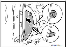
- Release the pawls using a suitable tool and then remove instrument side finisher (LH) by pulling rearward.
: Pawl
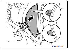
6. Release the pawls using a suitable tool and then remove instrument side finisher (RH) by pulling rearward.
: Pawl
- Remove center console lower. Refer to IP "Removal and Installation".
- Remove steering wheel. Refer to ST "Removal and Installation".
- Remove steering column covers. Refer to IP "Removal and Installation".
- Remove combination switch. Refer to EXL "Removal and Installation".
- Remove combination meter. Refer to MWI "Removal and Installation" (TYPE A) or MWI "Removal and Installation" (TYPE B).
- Remove cluster lid C. Refer to IP "Removal and Installation".
- Remove audio unit (if equiped), refer to AV "Removal and Installation" (BASE AUDIO) or AV "Removal and Installation" (MID AUDIO) or remove AV control unit, refer to AV "Removal and Installation" (NAVIGATION).
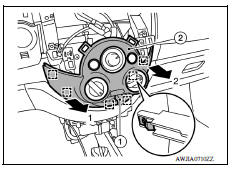
- Remove A/C control finisher.
a. Remove intake door lever knob (1).
b. Pull left side of A/C control finisher (2) rearward to release left side metal clips.
: Metal clip
c. Pull right side of A/C control finisher (2) rearward to release right side metal clips and remove A/C control finisher.
: Metal clip
- Remove A/C control. Refer to HAC "Removal and Installation".
- Remove glove box assembly. Refer to IP "Removal and Installation".
- Remove passenger air bag module. Refer to SR "Removal and Installation".
- Remove instrument panel assembly.
a. Remove instrument panel assembly screws (A).
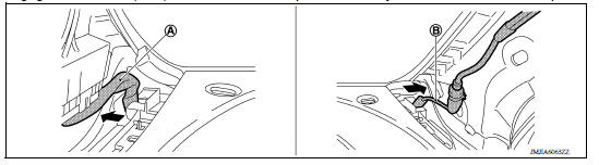
b. Disengage the harness (A, B) from the instrument panel assembly at the base of each front pillar.
c. Remove instrument panel assembly through passenger door opening.
CAUTION:
- Cover shift selector assembly with a shop cloth to prevent damage to instrument panel assembly.
- When removing instrument panel assembly, two people are required to prevent it from dropping.
19. Removal of the following components is only necessary if replacing the instrument panel assembly.
- Side ventilator grilles (LH/RH): Refer to VTL "SIDE VENTILATOR GRILLE : Removal and Installation".
- Center ventilator duct LH/RH: Refer to VTL "CENTER VENTILATOR DUCT : Removal and Installation".
INSTALLATION
Installation is in the reverse order of removal.
CAUTION:
- Do not reuse the steering wheel nut after removal, replace with a new nut.
- Do not reuse the passenger air bag bolts after removal, replace with new bolts.
 Squeak and rattle trouble diagnoses
Steering column covers
Removal and Installation REMOVAL Remove instrument lower panel LH. Refer to IP "Removal and Installation". Remove lower knee protector (LH) bolts and lower knee protector (LH). ...
Other materials:
Trunk lid trim
Exploded View
1. Trunk lid assembly 2. Trunk lid finisher
Removal and Installation
REMOVAL
Fully open trunk lid.
Remove emergency release handle. Refer to DLK "EMERGENCY LEVER : Removal
and Installation".
Disconnect the harness connector (A) from the trunk lid lock
as ...
Warning function
WARNING FUNCTION : System Description
OPERATION DESCRIPTION
The warning function are as per the following items and are given to the user
as warning information and
warnings using combinations of Intelligent Key warning buzzer, combination meter
buzzer, KEY warning lamp,
shift P warning lamp ...
Categories
- Manuals Home
- Nissan Versa Owners Manual
- Nissan Versa Service Manual
- Video Guides
- Questions & Answers
- External Resources
- Latest Updates
- Most Popular
- Sitemap
- Search the site
- Privacy Policy
- Contact Us

0.0054