Nissan Versa (N17): Jump starting
To start your engine with a booster battery, the instructions and precautions below must be followed.
WARNING
- If done incorrectly, jump starting can lead to a battery explosion, resulting in severe injury or death. It could also damage your vehicle.
- Explosive hydrogen gas is always present in the vicinity of the battery. Keep all sparks and flames away from the battery.
- Do not allow battery fluid to come into contact with eyes, skin, clothing or painted surfaces. Battery fluid is a corrosive sulfuric acid solution which can cause severe burns. If the fluid should come into contact with anything, immediately flush the contacted area with water.
- Keep battery out of the reach of children.
- The booster battery must be rated at 12 volts. Use of an improperly rated battery can damage your vehicle.
- Whenever working on or near a battery, always wear suitable eye protectors (for example, goggles or industrial safety spectacles) and remove rings, metal bands, or any other jewelry. Do not lean over the battery when jump starting.
- Do not attempt to jump start a frozen battery. It could explode and cause serious injury.
- Your vehicle has an automatic engine cooling fan. It could come on at any time. Keep hands and other objects away from it.

WARNING
Always follow the instructions below. Failure to do so could result in damage to the charging system and cause personal injury.
1. If the booster battery is in another vehicle, position the 2 vehicles to bring their batteries near each other.
Do not allow the 2 vehicles to touch.
2. Apply the parking brake. Move the shift lever to N (Neutral) (manual transmission) or to P (Park) (Continuously Variable Transmission)/(automatic transmission).
Switch off all unnecessary electrical systems (lights, heater, air conditioner, etc.).
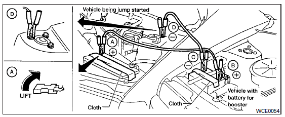
3. Remove vent caps on the battery (if so equipped). Cover the battery with an old cloth to reduce explosion hazard.
4. Connect jumper cables in the sequence illustrated ( A , B , C , D ).
CAUTION
- Always connect positive ( +) to positive (+ ) and negative (- ) to body ground (for example, strut mounting bolt, engine lift bracket, etc.) - not to the battery.
- Make sure the jumper cables do not touch moving parts in the engine compartment and that the cable clamps do not contact any other metal.
5. Start the engine of the booster vehicle and let it run for a few minutes.
6. Keep the engine speed of the booster vehicle at about 2,000 rpm, and start the engine of the vehicle being jump started.
CAUTION
Do not keep the starter motor engaged for more than 10 seconds. If the engine does not start right away, turn the key off and wait 3 to 4 seconds before trying again.
7. After starting the engine, carefully disconnect the negative cable and then the positive cable.
8. Replace the vent caps (if so equipped). Be sure to dispose of the cloth used to cover the vent holes as it may be contaminated with corrosive acid.
Push starting
CAUTION Do not push start this vehicle. The three-way catalyst may be damaged Continuously Variable Transmission (CVT) and Manual Transmission models cannot be push-started or tow-started. ...
Other materials:
P0706 Transmission range sensor A
DTC Logic
DTC DETECTION LOGIC
DTC
Trouble diagnosis name
DTC detection condition
Possible causes
P0706
Transmission Range Sensor
"A" Circuit Range/Performance
The following diagnosis conditions
are met and the position
signal is OFF continuously for
15 ...
EPS Warning lamp
Component Function Check
1.CHECK THE ILLUMINATION OF THE EPS WARNING LAMP
Check that the EPS warning lamp turns ON when ignition switch turns ON. Then,
EPS warning lamp turns
OFF after the engine is started.
Is the inspection result normal?
YES >> Inspection End.
NO >> Perform t ...
Categories
- Manuals Home
- Nissan Versa Owners Manual
- Nissan Versa Service Manual
- Video Guides
- Questions & Answers
- External Resources
- Latest Updates
- Most Popular
- Sitemap
- Search the site
- Privacy Policy
- Contact Us
0.0058

 Flat tire