Nissan Versa (N17): L Terminal circuit (open)
Description
The "L" terminal circuit controls the charge warning lamp. The charge warning lamp turns ON when the ignition switch is set to ON or START. When the generator is providing sufficient voltage with the engine running, the charge warning lamp turns OFF. If the charge warning lamp illuminates with the engine running, a malfunction is indicated.
Diagnosis Procedure
Regarding Wiring Diagram information. Refer to CHG "Wiring Diagram".
1.CHECK "L" TERMINAL CONNECTION
1. Turn ignition switch OFF.
2. Check if "L" terminal is clean and tight.
Is the inspection result normal?
YES >> GO TO 2.
NO >> Repair "L" terminal connection. Confirm repair by performing complete Charging system test using EXP-800 NI or GR8-1200 NI (if available). Refer to applicable Instruction Manual for proper testing procedures.
2.CHECK "L" TERMINAL CIRCUIT (OPEN)
1. Disconnect the generator connector.
2. Apply ground to generator harness connector terminal.
3. Check condition of the charge warning lamp with the ignition switch in the
ON position.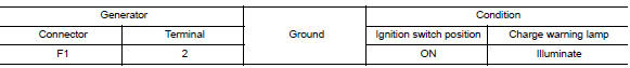
Does it illuminate?
YES >> "L" terminal circuit is normal. Refer to CHG "Work Flow (With EXP-800 NI or GR8-1200 NI)" or CHG "Work Flow (Without EXP-800 NI or GR8-1200 NI)".
NO >> GO TO 3.
3.CHECK HARNESS CONTINUITY (OPEN CIRCUIT)
1. Disconnect the battery cable from the negative terminal.
2. Disconnect the combination meter connector.
3. Check continuity between generator harness connector and combination meter harness connector.
Combination meter Type B

Combination meter Type A

is the inspection result normal?
YES >> GO TO 4.
NO >> Repair or replace the harness or connectors.
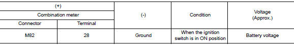
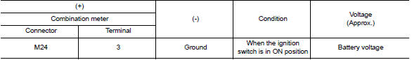
4.CHECK POWER SUPPLY CIRCUIT
1. Connect the battery cable to the negative terminal.
2. Check voltage between combination meter harness connector and ground.
Combination meter Type B
Combination meter Type A
Is the inspection result normal?
YES >> Replace the combination meter. Refer to MWI "Removal and Installation" (Type A) or MWI"Removal and Installation" (Type B).
NO >> Repair or replace the harness or connectors.
 B Terminal circuit
Description "B" terminal circuit supplies power to charge the battery and to operate the vehicles electrical system. Diagnosis Procedure Regarding Wiring Diagram information. Refer to CHG "W ...
L Terminal circuit (short)
Description The terminal "L" circuit controls the charge warning lamp. The charge warning lamp turns ON when the ignition switch is set to ON or START. When the generator is providing sufficient v ...
Other materials:
Shift control
SHIFT CONTROL : System Description
SYSTEM DIAGRAM
DESCRIPTION
To select the gear ratio that can give the driving force to meet driver's
intent or vehicle situation, the vehicle
driving condition such as vehicle speed or accelerator pedal position is
detected and the most appropriate
g ...
Pedal vibration or ABS operation
sound occurs
Diagnosis Procedure
CAUTION:
Under the following conditions, ABS is activated and vibration is felt when
brake pedal is lightly
depressed (just place a foot on it). However, this is normal.
When shifting gears
When driving on slippery road
During cornering at high speed
When passing o ...
Categories
- Manuals Home
- Nissan Versa Owners Manual
- Nissan Versa Service Manual
- Video Guides
- Questions & Answers
- External Resources
- Latest Updates
- Most Popular
- Sitemap
- Search the site
- Privacy Policy
- Contact Us

0.0048