Nissan Versa (N17): Shift control
SHIFT CONTROL : System Description
SYSTEM DIAGRAM
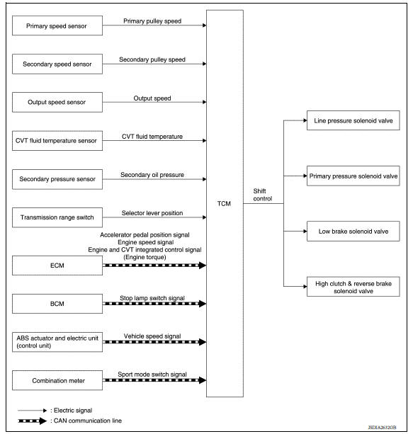
DESCRIPTION
To select the gear ratio that can give the driving force to meet driver's intent or vehicle situation, the vehicle driving condition such as vehicle speed or accelerator pedal position is detected and the most appropriate gear ratio is selected and the shifting method before reaching the speed is determined. The information is output to the primary pressure solenoid valve to control the line pressure input/output to the primary pulley, to determine the primary pulley (movable pulley) position and to control the gear position.
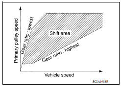
D Position (Normal)
Gear shifting is performed in all shifting ranges from the lowest to the highest gear ratio.
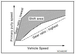
D Position (Sport)
The gear ratio is generally high by limiting the shifting range on the high side, and this always generates a large driving power.
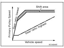
L Position
By limiting the shifting range only to the lowest of the gear ratio, a large driving force and engine brake are obtained.
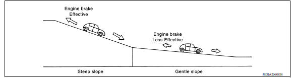
Hill Climbing And Descending Control
If a downhill is detected with the accelerator pedal is released, the system performs downshift to increase the engine brake force so that vehicle may not be accelerated more than necessary. If a climbing hill is detected, the system improves the acceleration performance in re-acceleration by limiting the gear shift range on the high side.
NOTE: For engine brake control on a downhill, the control can be stopped with CONSULT.
Control In Acceleration
From change of the vehicle speed or accelerator pedal position, the acceleration request level of the driver or driving scene is evaluated. In start or acceleration during driving, the gear shift characteristics with linearity of revolution increase and vehicle speed increase are gained to improve the acceleration feel.
SELECT CONTROL
SELECT CONTROL : System Description
SYSTEM DIAGRAM
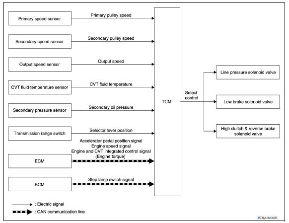
DESCRIPTION
Based on accelerator pedal angle, engine speed, primary pulley speed, and the secondary pulley speed, the optimum operating pressure is set to reduce impact of a selector lever operation while shifting from "N" ("P") to "D" ("R") position.
 Line pressure control
LINE PRESSURE CONTROL : System Description SYSTEM DIAGRAM DESCRIPTION Highly accurate line pressure control (secondary pressure control) reduces friction for improvement of fuel economy. No ...
Lock-up control
LOCK-UP CONTROL : System Description SYSTEM DIAGRAM DESCRIPTION Controls for improvement of the transmission efficiency by engaging the torque converter clutch in the torque converter ...
Other materials:
Multiport fuel injection system
MULTIPORT FUEL INJECTION SYSTEM : System Diagram
MULTIPORT FUEL INJECTION SYSTEM : System
Description
INPUT/OUTPUT SIGNAL CHART
Sensor
Input signal to ECM
ECM function
Actuator
Crankshaft position sensor (POS)
Engine speed*4
Piston position
Fuel injection & ...
Driver air bag module
Exploded View
1. Driver air bag module 2. Steering wheel
Removal and Installation
WARNING:
Always observe the following items for preventing accidental activation.
Before servicing, turn ignition switch OFF, disconnect both
battery terminals, then wait at least three
minutes or mor ...
Categories
- Manuals Home
- Nissan Versa Owners Manual
- Nissan Versa Service Manual
- Video Guides
- Questions & Answers
- External Resources
- Latest Updates
- Most Popular
- Sitemap
- Search the site
- Privacy Policy
- Contact Us

0.0048