Nissan Versa (N17): Line pressure control
LINE PRESSURE CONTROL : System Description
SYSTEM DIAGRAM
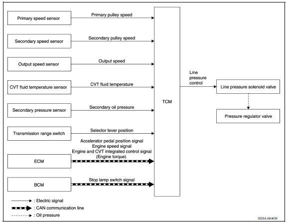
DESCRIPTION
Highly accurate line pressure control (secondary pressure control) reduces friction for improvement of fuel economy.
Normal Oil Pressure Control
Appropriate line pressure and secondary pressure suitable for driving condition are determined based on the accelerator pedal position, engine speed, primary pulley (input) speed, secondary pulley (output) speed, vehicle speed, input torque, stop lamp switch signal, transmission range switch signal, lock-up signal, power voltage, target shift ratio, oil temperature and oil pressure.
Secondary Pressure Feedback Control
In normal oil pressure control and oil pressure control in shifting, highly accurate secondary pressure is determined by detecting the secondary pressure using a oil pressure sensor and by feedback control.
 CVT Control system
Shift control
SHIFT CONTROL : System Description SYSTEM DIAGRAM DESCRIPTION To select the gear ratio that can give the driving force to meet driver's intent or vehicle situation, the vehicle driving con ...
Other materials:
Fuel efficient driving tips
Follow these easy-to-use Fuel Efficient Driving
Tips to help you achieve the most fuel economy
from your vehicle.
1. Use Smooth Accelerator and Brake
Pedal Application
Avoid rapid starts and stops.
Use smooth, gentle accelerator and
brake application whenever possible.
Maintain constan ...
Main power supply and ground circuit
Diagnosis Procedure
1.CHECK TCM POWER CIRCUIT 1
Turn the ignition switch OFF.
Disconnect the TCM connector.
Check the voltage between the TCM harness connector terminals and
ground.
Is the inspection result normal?
YES >> GO TO 2.
NO >> GO TO 4.
2.CHECK TCM POWER ...
Categories
- Manuals Home
- Nissan Versa Owners Manual
- Nissan Versa Service Manual
- Video Guides
- Questions & Answers
- External Resources
- Latest Updates
- Most Popular
- Sitemap
- Search the site
- Privacy Policy
- Contact Us

0.0052