
Nissan Versa (N17): Microphone
Removal and Installation
1. Remove the microphone (1) from the headlining using a suitable tool.
 Clip
Clip
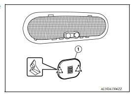
2. Disconnect the harness connector from microphone and remove.
INSTALLATION
Installation is in the reverse order of removal.
ANTENNA FEEDER
Feeder Layout
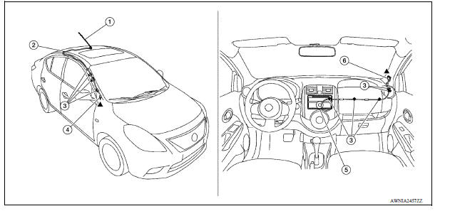
1. Antenna mast 2. Antenna feed 3. Clip 4. Harness connector 5. Audio unit 6. Harness connector
DISPLAY AUDIO
 Bluetooth control unit
Removal and Installation REMOVAL 1. Remove the trunk floor finisher. 2. Remove the trunk rear finisher. 3. Remove the trunk side finisher (RH) 4. Disconnect the harness connector (A) from Bluet ...

Other materials:
Oil pan (upper) and oil strainer
Exploded View
1. Rear oil seal 2. Oring 3. Oil pan (upper)
4. Oil pump chain tensioner (for oil
pump drive chain)
5. Oil pump drive chain 6. Crankshaft key
7. Crankshaft sprocket 8. Oil pump sprocket 9. Oil pump
10. Oring 11. Oring 12. Oil pan drain plug
13. Drain plug washer 14. Oil pan ...
Brake pad
BRAKE PAD : Inspection and Adjustment
INSPECTION
Check brake pad wear thickness from an inspection hole on cylinder
body. Check using a scale if necessary.
Wear thickness : Refer to BR "Front Disc Brake".
ADJUSTMENT
Burnish contact surfaces between disc rotor and brake pads a ...
Categories
- Manuals Home
- Nissan Versa Owners Manual
- Nissan Versa Service Manual
- Video Guides
- Questions & Answers
- External Resources
- Latest Updates
- Most Popular
- Sitemap
- Search the site
- Privacy Policy
- Contact Us

0.0072