Nissan Versa (N17): Oil pan (upper) and oil strainer
Exploded View
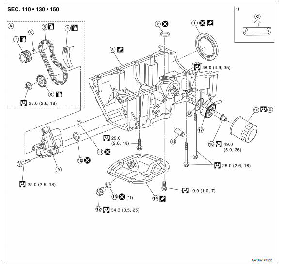
1. Rear oil seal 2. Oring 3. Oil pan (upper) 4. Oil pump chain tensioner (for oil pump drive chain) 5. Oil pump drive chain 6. Crankshaft key 7. Crankshaft sprocket 8. Oil pump sprocket 9. Oil pump 10. Oring 11. Oring 12. Oil pan drain plug 13. Drain plug washer 14. Oil pan (lower) 15. Oil filter 16. Connector bolt 17. Oil cooler 18. Oring 19. Relief valve
Removal and Installation
NOTE:
The oil strainer is included in the oil pan (upper) and cannot be removed.
REMOVAL
- Remove the oil pan (lower).
- Remove oil pump sprocket and crankshaft sprocket together with oil pump drive chain.
- Remove oil pan (upper).
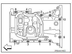
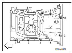
a. Loosen oil pan (upper) bolts in the reverse of the order as shown
 : Engine front
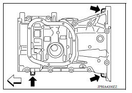
b. Insert a suitable tool into the arrow ( ) as shown and open up a
crack between the oil pan (upper) cylinder block.
) as shown and open up a
crack between the oil pan (upper) cylinder block.
: Engine front
c. Insert the Tool between the oil pan (upper) and cylinder block.
Slide Tool by tapping on the side of Tool with a hammer.
Tool number : KV10111100 (J37228)
CAUTION:
- Be careful not to damage the mating surface.
- The liquid gasket used at the factory is very strong. Pry only in the areas shown.
- Do not remove oil pump and oil strainer from oil pan (upper).
4. Remove rear oil seal from crankshaft.
INSTALLATION
CAUTION:
Do not reuse Orings or washers.
1. Install the oil pan (upper):
a. Use scraper to remove old liquid gasket from mating surfaces.
- Also remove the old liquid gasket from mating surface of cylinder block.
- Remove old liquid gasket from the bolt holes and threads.
CAUTION:
Do not scratch or damage the mating surfaces when cleaning off old liquid gasket.
b. Install Oring to the cylinder block.
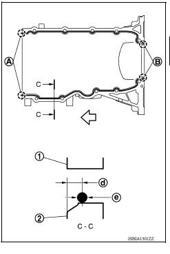
c. Apply a continuous bead of liquid gasket with the Tool or suitable tool to areas as shown.
Use Genuine Silicone RTV Sealant or equivalent.
(1) : Cylinder block
(2) : Oil pan (upper)
(A) : 2 mm (0.07 in) protruded to outside
(B) : 2 mm (0.07 in) protruded to rear oil seal mounting side
(d) : 5.5 7.5 mm (0.217 0.295 in)
(e) : 4.0 5.0 mm (0.157 0.197 in) diameter
: Engine front side
CAUTION:
Attaching should be done within 5 minutes after coating.
d. Tighten bolts in the numerical order as shown.
: Engine front
CAUTION:
Install avoiding misalignment of both oil pan gasket and Oring.
- The bolts are different according to the installation position.
Refer to the numbers as shown.
M8×180 mm (7.09 in) : No. 9, 10
M8×25 mm (0.98 in) : No. 4, 7, 8
M8×90 mm (3.54 in) : No. 1, 2, 3, 5, 6
2. Install rear oil seal:
CAUTION:
- The installation of rear oil seal should be completed within 5 minutes after installing oil pan (upper).
- Do not touch oil seal lip.
a. Wipe off any liquid gasket protruding to the rear oil seal mounting part of oil pan (upper) and cylinder block using a suitable tool.
b. Apply the liquid gasket lightly to entire outside area of new rear oil seal.
Use Genuine Liquid Gasket or equivalent.
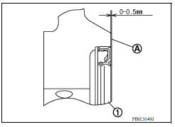
c. Pressfit the rear oil seal using a drift with outer diameter 113 mm (4.45 in) and inner diameter 90 mm (3.54 in) (commercial service tool) (A).
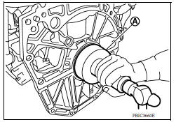
- Pressfit to the dimensions specified as shown.
(1) : Rear oil seal
(A) : Rear end surface of cylinder block
CAUTION:
- Do not touch the grease applied to the oil seal lip.
- Be careful not to damage the rear oil seal mounting part of oil pan (upper) and cylinder block or the crankshaft.
- Pressfit straight and check that oil seal does not curl or tilt.
d. After pressfitting the rear oil seal, completely wipe off any liquid gasket protruding to rear end surface side.
3. Installation of the remaining components is in the reverse order of removal.
4. Add the specified oil after waiting for at least 30 minutes.
CAUTION:
- The components must be installed within 5 minutes of the liquid gasket application.
- Allow 30 minutes for the liquid gasket to set before adding oil to the engine.
INSPECTION AFTER INSTALLATION
- Before starting engine, check oil/fluid levels, including engine coolant and engine oil. If less than required quantity, fill to the specified level.
- Use procedure below to check for fuel leakage.
- Turn ignition switch ON (with engine stopped). With fuel pressure applied to fuel piping, check for fuel leakage at connection points.
- Start engine. With engine speed increased, check again for fuel leakage at connection points.
- Run engine to check for unusual noise and vibration.
NOTE:
If hydraulic pressure inside timing chain tensioner drops after removal and installation, slack in the guide may generate a pounding noise during and just after engine start. However, this is normal. Noise will stop after hydraulic pressure rises.
- Warm up engine thoroughly to make sure there is no leakage of fuel, exhaust gas, or any oils/fluids including engine oil and engine coolant.
- Bleed air from passages in lines and hoses, such as in cooling system.
- After cooling down engine, again check oil/fluid levels including engine oil and engine coolant. Refill to specified level, if necessary.
- Summary of the inspection items:
| Item | Before starting engine | Engine running | After engine stopped | |
| Engine coolant | Level | Leakage | Level | |
| Engine oil | Level | Leakage | Level | |
| Transmission/ transaxle fluid | A/T and CVT Models | Leakage | Level/Leakage | Leakage |
| M/T Models | Level/Leakage | Leakage | Level/Leakage | |
| Other oils and fluids* | Level | Leakage | Level | |
| Fuel | Leakage | Leakage | Leakage | |
| Exhaust gas | Leakage | |||
*Power steering fluid, brake fluid, etc.
 Engine stand setting
Setting NOTE: The following procedures explain how to disassemble the engine with the engine stand fastened to the bell housing. Some steps may be different if using a different type of engine ...
Cylinder block
Exploded View 1. Crankshaft position sensor cover 2. Crankshaft position sensor (POS) 3. Oring 4. Drain plug 5. Cylinder block 6. Oil level gauge 7. Oil level gauge guide 8. Oring 9. Knock s ...
Other materials:
Air cleaner
WARNING
Operating the engine with the air
cleaner filter off can cause you or others
to be burned. The air cleaner filter not
only cleans the intake air, it also stops
the flame if the engine backfires. If the
air cleaner is not installed and the engine
backfires, you could be burn ...
Final drive
Exploded View
1. Differential side bearing outer race 2. Differential side bearing 3. Final
drive
: Replace the parts as a set.
Disassembly
Remove differential side bearings, using Tool (A) and suitable tool.
Tool number : ST33052000 ( - )
Assembly
Install differential sid ...
Categories
- Manuals Home
- Nissan Versa Owners Manual
- Nissan Versa Service Manual
- Video Guides
- Questions & Answers
- External Resources
- Latest Updates
- Most Popular
- Sitemap
- Search the site
- Privacy Policy
- Contact Us

0.005