Nissan Versa (N17): Parking, license plate and tail lamps are not turned on
Description
The parking, license plate and tail lamps do not turn ON in any combination switch (lighting and turn signal switch) position.
Diagnosis Procedure
1.COMBINATION SWITCH (LIGHTING AND TURN SIGNAL SWITCH) INSPECTION
Check the combination switch (lighting and turn signal switch). Refer to BCS"Symptom Table" (with Intelligent Key) or BCS "Symptom Table" (without Intelligent Key).
Is the combination switch (lighting and turn signal switch) normal?
YES >> GO TO 2.
NO >> Repair or replace the malfunctioning part.
2.CHECK TAIL LAMP RELAY REQUEST SIGNAL INPUT
CONSULT DATA MONITOR
- Select TAIL & CLR REQ of IPDM E/R DATA MONITOR item.
- While operating the combination switch (lighting and turn signal
switch), check the monitor status.
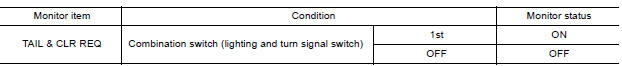
Is the item status normal?
YES >> GO TO 3.
NO >> Replace BCM. Refer to BCS "Removal and Installation" (with Intelligent Key) or BCS "Removal and Installation" (without Intelligent Key).
3.PARK LAMP CIRCUIT INSPECTION
Check the parking lamp circuit. Refer to EXL "PARKING, LICENSE PLATE AND TAIL LAMP SYSTEM : System Description".
Is the tail lamp circuit normal?
YES >> Replace IPDM E/R. Refer to PCS "Removal and Installation" (with Intelligent Key) or PCS "Removal and Installation" (without Intelligent Key).
NO >> Repair or replace the malfunctioning part.
 Both side headlamps (LO) are not
turned on
Both side headlamps (LO) are not
turned on
Description The headlamps (both sides) do not turn ON in any combination switch (lighting and turn signal switch) setting. Diagnosis Procedure 1.COMBINATION SWITCH (LIGHTING AND TURN SIGNAL SWIT ...
Both side front fog lamps are not
turned on
Description The front fog lamps do not turn ON in any setting. Diagnosis Procedure 1.COMBINATION SWITCH (LIGHTING AND TURN SIGNAL SWITCH) INSPECTION Check the combination switch (lighting and tu ...
Other materials:
Power outlets
Instrument panel
Console (if so equipped)
The power outlets are for powering electrical
accessories such as cellular telephones. The
outlets are rated at 12 volt, 120W (10A) maximum.
CAUTION
The outlet and plug may be hot during
or immediately after use.
Only certain power outlets ...
Fuel-filler door
Opener operation
The fuel-filler door release is located below the
instrument panel. To open the fuel-filler door, pull
the release. To lock, close the fuel-filler door
securely.
Fuel-filler cap
WARNING
Gasoline is extremely flammable and
highly explosive under certain conditions.
...
Categories
- Manuals Home
- Nissan Versa Owners Manual
- Nissan Versa Service Manual
- Video Guides
- Questions & Answers
- External Resources
- Latest Updates
- Most Popular
- Sitemap
- Search the site
- Privacy Policy
- Contact Us

0.0058