Nissan Versa (N17): Precautions
Precaution for Supplemental Restraint System (SRS) "AIR BAG" and "SEAT BELT PRE-TENSIONER"
The Supplemental Restraint System such as "AIR BAG" and "SEAT BELT PRE-TENSIONER", used along with a front seat belt, helps to reduce the risk or severity of injury to the driver and front passenger for certain types of collision. This system includes seat belt switch inputs and dual stage front air bag modules. The SRS system uses the seat belt switches to determine the front air bag deployment, and may only deploy one front air bag, depending on the severity of a collision and whether the front occupants are belted or unbelted.
Information necessary to service the system safely is included in the SR and SB section of this Service Manual.
WARNING:
- To avoid rendering the SRS inoperative, which could increase the risk of personal injury or death in the event of a collision which would result in air bag inflation, all maintenance must be performed by an authorized NISSAN/INFINITI dealer.
- Improper maintenance, including incorrect removal and installation of the SRS, can lead to personal injury caused by unintentional activation of the system. For removal of Spiral Cable and Air Bag Module, see the SR section.
- Do not use electrical test equipment on any circuit related to the SRS unless instructed to in this Service Manual. SRS wiring harnesses can be identified by yellow and/or orange harnesses or harness connectors.
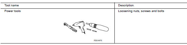
PRECAUTIONS WHEN USING POWER TOOLS (AIR OR ELECTRIC) AND HAMMERS
WARNING:
- When working near the Airbag Diagnosis Sensor Unit or other Airbag System sensors with the Ignition ON or engine running, DO NOT use air or electric power tools or strike near the sensor(s) with a hammer. Heavy vibration could activate the sensor(s) and deploy the air bag(s), possibly causing serious injury.
- When using air or electric power tools or hammers, always switch the Ignition OFF, disconnect the battery, and wait at least 3 minutes before performing any service.
General Precautions
WARNING:
When replacing fuel line parts, be sure to observe the following.
- Put a "CAUTION: FLAMMABLE" sign in the workshop.
- Be sure to work in a well ventilated area and furnish workshop with a CO2 fire extinguisher.
- Do not smoke while servicing fuel system. Keep open flames and sparks away from the work area.
CAUTION:
- Use gasoline required by the regulations for octane number. Refer to GI, "Fuel (Regular Unleaded Gasoline Recommended) HR16DE".
- Before removing fuel line parts, perform the following procedures:
- Put drained fuel in an explosion-proof container and put the lid on securely. Keep the container in safe area.
- Release fuel pressure from the fuel lines. Refer to EC, "Work Procedure".
- Disconnect the battery cable from the negative terminal.
- Always replace O-ring and clamps with new ones.
- Do not kink or twist tubes when they are being installed.
- Do not tighten hose clamps excessively to avoid damaging hoses.
- After installing tubes, check there is no fuel leakage at connections in the following steps.
- Apply fuel pressure to fuel lines with turning ignition switch "ON" (with engine stopped). Then check for fuel leakage at connections.
- Start engine and rev it up and check for fuel leakage at connections.
- Use only a Genuine NISSAN fuel filler cap as a replacement. If an incorrect fuel filler cap is used, the MIL may come on.
- For servicing "EVAPORATIVE EMISSION SYSTEM" parts, refer to EC, "EVAPORATIVE EMISSION SYSTEM : System Diagram".
PREPARATION
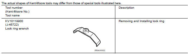
Special Service Tool
Commercial Service Tools
FUEL SYSTEM
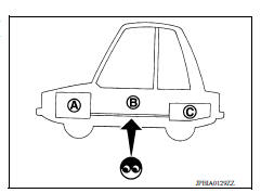
Inspection
Inspect fuel lines, fuel filler cap, and fuel tank for improper attachment, leakage, cracks, damage, loose connections, chafing or deterioration.
(A) : Engine
(B) : Fuel line
(C) : Fuel tank
If necessary, repair or replace damaged parts.
Quick Connector
CAUTION:
- After connecting fuel tube quick connectors, check quick connectors are secure.
- Ensure that connector and resin tube do not contact any adjacent parts.
 Service data and specifications
(SDS)
Service data and specifications
(SDS)
Idle Speed *: Under the following conditions A/C switch: OFF Electric load: OFF (Lights, heater fan & rear window defogger) Steering wheel: Kept in straight-ahead pos ...
Fuel level sensor unit, fuel filter and fuel pump assembly
Exploded View 1. Lock ring 2. Fuel level sensor unit, fuel filter and fuel pump assembly 3. O-ring 4. Fuel tank Removal and Installation WARNING: Be sure to read "General Precautions" befor ...
Other materials:
Event Data Recorders (EDR)
This vehicle is equipped with an Event Data Recorder
(EDR). The main purpose of an EDR is to
record, in certain crash or near crash-like situations,
such as an air bag deployment or hitting a
road obstacle, data that will assist in understanding
how a vehicle's systems performed. The EDR
is de ...
U0300 Can communication data
Description
The amount of data transmitted from each control unit is read.
DTC Logic
DTC DETECTION LOGIC
DTC
Trouble diagnosis name
DTC detection condition
Possible causes
U0300
Internal Control Module Software
Incompatibility
When the amount of data transmitt ...
Categories
- Manuals Home
- Nissan Versa Owners Manual
- Nissan Versa Service Manual
- Video Guides
- Questions & Answers
- External Resources
- Latest Updates
- Most Popular
- Sitemap
- Search the site
- Privacy Policy
- Contact Us

0.0052