Nissan Versa (N17): Precautions
Precaution for Supplemental Restraint System (SRS) "AIR BAG" and "SEAT BELT PRE-TENSIONER"
The Supplemental Restraint System such as "AIR BAG" and "SEAT BELT PRE-TENSIONER", used along with a front seat belt, helps to reduce the risk or severity of injury to the driver and front passenger for certain types of collision. This system includes seat belt switch inputs and dual stage front air bag modules. The SRS system uses the seat belt switches to determine the front air bag deployment, and may only deploy one front air bag, depending on the severity of a collision and whether the front occupants are belted or unbelted.
Information necessary to service the system safely is included in the SR and SB section of this Service Manual.
WARNING:
- To avoid rendering the SRS inoperative, which could increase the risk of personal injury or death in the event of a collision which would result in air bag inflation, all maintenance must be performed by an authorized NISSAN/INFINITI dealer.
- Improper maintenance, including incorrect removal and installation of the SRS, can lead to personal injury caused by unintentional activation of the system. For removal of Spiral Cable and Air Bag Module, see the SR section.
- Do not use electrical test equipment on any circuit related to the SRS unless instructed to in this Service Manual. SRS wiring harnesses can be identified by yellow and/or orange harnesses or harness connectors.
PRECAUTIONS WHEN USING POWER TOOLS (AIR OR ELECTRIC) AND HAMMERS
WARNING:
- When working near the Airbag Diagnosis Sensor Unit or other Airbag System sensors with the Ignition ON or engine running, DO NOT use air or electric power tools or strike near the sensor(s) with a hammer. Heavy vibration could activate the sensor(s) and deploy the air bag(s), possibly causing serious injury.
- When using air or electric power tools or hammers, always switch the Ignition OFF, disconnect the battery, and wait at least 3 minutes before performing any service.
PREPARATION
Special Service Tool
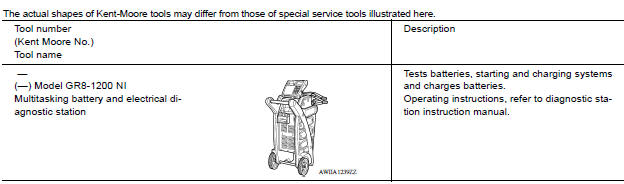
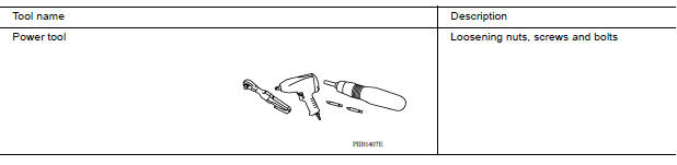
Commercial Service Tools
COMPONENT PARTS
STARTING SYSTEM (WITHOUT INTELLIGENT KEY)
STARTING SYSTEM (WITHOUT INTELLIGENT KEY) : Component Parts Location
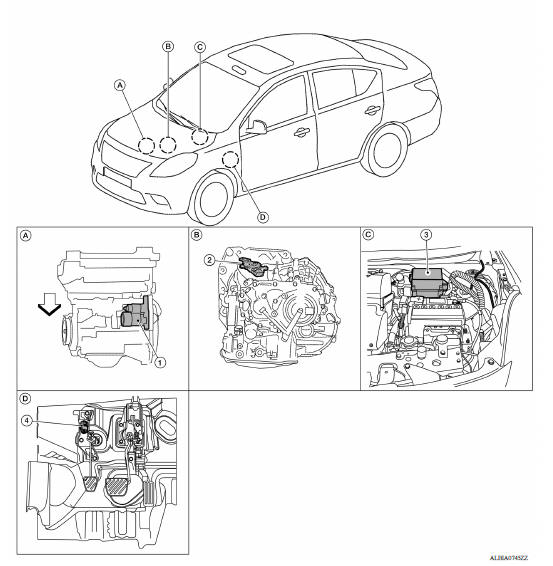
 :Vehicle front
1. Starter motor 2. Transmission range switch (CVT or
A/T Models)
3. IPDM E/R
4. Clutch interlock switch (M/T Models)
:Vehicle front
1. Starter motor 2. Transmission range switch (CVT or
A/T Models)
3. IPDM E/R
4. Clutch interlock switch (M/T Models)
STARTING SYSTEM (WITHOUT INTELLIGENT KEY) : Component Description
| Component part | Description |
| Starter motor | The starter motor plunger closes and the motor is supplied with battery power, which in turn cranks the engine, when the S terminal is supplied with electric power. |
| Transmission range switch (CVT or A/T Models) | Supplies power to the starter control relay (inside IPDM E/R) when the selector lever is shifted into the P or N position. |
| IPDM E/R | CPU inside IPDM E/R operates the starter control relay when the ignition switch is in the start position. |
| Clutch interlock switch (M/T Models) | Clutch interlock switch supplies power to the coil side of the starter control relay when the clutch pedal is depressed to crank the engine. |
STARTING SYSTEM (WITH INTELLIGENT KEY)
STARTING SYSTEM (WITH INTELLIGENT KEY) : Component Parts Location
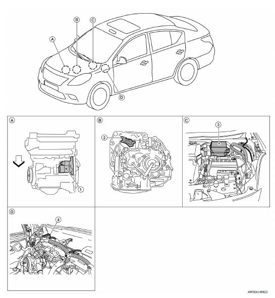
 Vehicle front
1. Starter motor 2. Transmission range switch 3. IPDM E/R
4. BCM (view with instrument panel
removed)
Vehicle front
1. Starter motor 2. Transmission range switch 3. IPDM E/R
4. BCM (view with instrument panel
removed)
STARTING SYSTEM (WITH INTELLIGENT KEY) : Component Description
| Component part | Description |
| BCM | BCM controls the starter relay. |
| IPDM E/R | CPU inside IPDM E/R operates the starter control relay when the ignition switch is in the start position. |
| Transmission range switch | Supplies power to the starter relay and starter control relay (inside IPDM E/R) when the selector lever is shifted into the P or N position. |
| Starter relay | Supplies power to starter control relay inside the IPDM E/R. |
| Starter motor | The starter motor plunger closes and the motor is supplied with battery power, which in turn cranks the engine, when the S terminal is supplied with electric power. |
SYSTEM
STARTING SYSTEM (WITHOUT INTELLIGENT KEY)
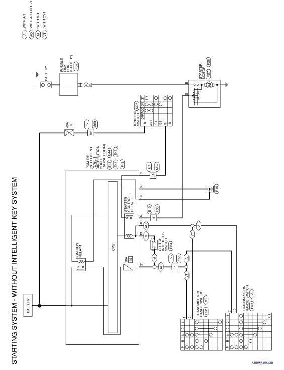
STARTING SYSTEM (WITHOUT INTELLIGENT KEY) : System Diagram
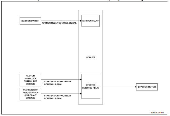
STARTING SYSTEM (WITHOUT INTELLIGENT KEY) : System Description
The starter motor plunger closes and provides a closed circuit between the battery and the starter motor. The starter motor is grounded to the cylinder block. With power and ground supplied, the starter motor operates.
STARTING SYSTEM (WITH INTELLIGENT KEY)
STARTING SYSTEM (WITH INTELLIGENT KEY) : System Diagram
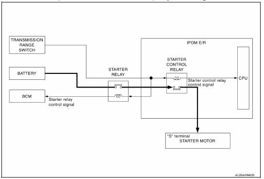
STARTING SYSTEM (WITH INTELLIGENT KEY) : System Description
- When the selector lever is in the P or N position, power is supplied to starter relay and starter control relay by the transmission range switch. The BCM and IPDM E/R (CPU) will detect the selector lever position by the input signal.
- When the starter operating condition is meet, the IPDM E/R will turn the starter control relay ON by starter control relay control signal.
- When engine cranking condition is meet, the BCM turns ON the starter relay by starter control relay signal.
- Then battery power is supplied to starter motor ("S" terminal) through the starter control relay and starter relay.
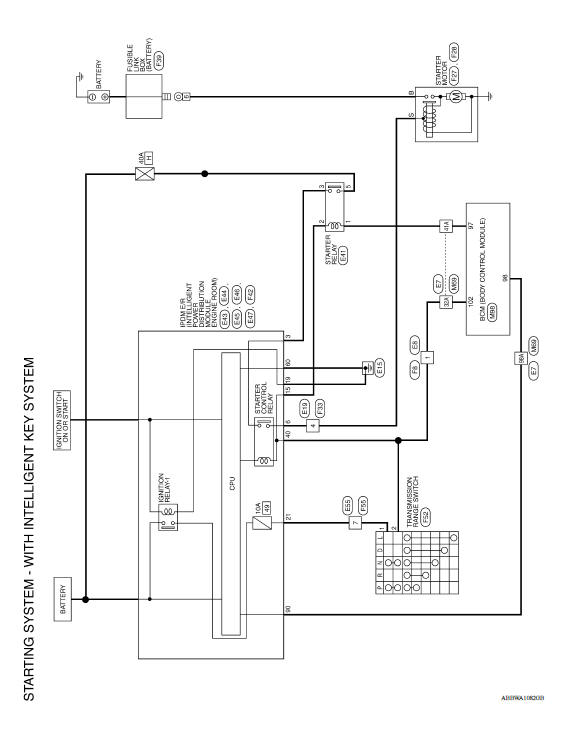
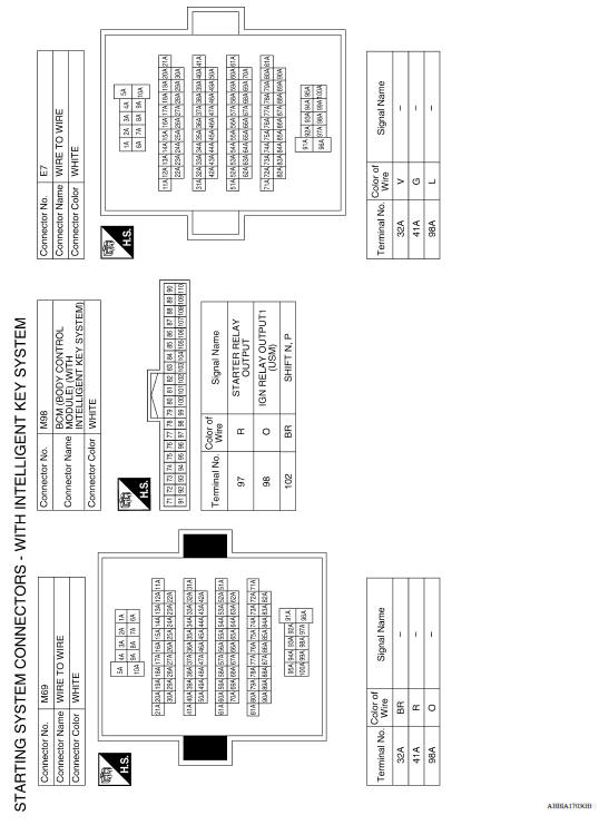
STARTING SYSTEM
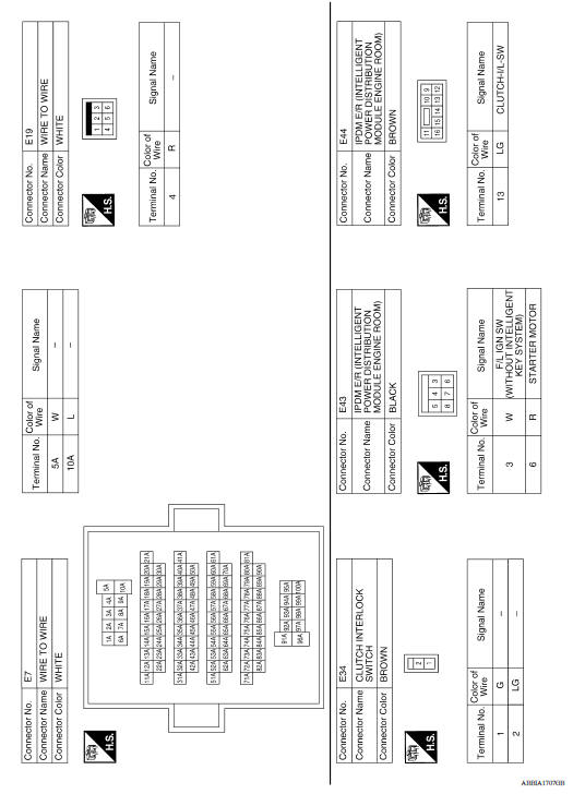
Wiring Diagram - With Intelligent Key System
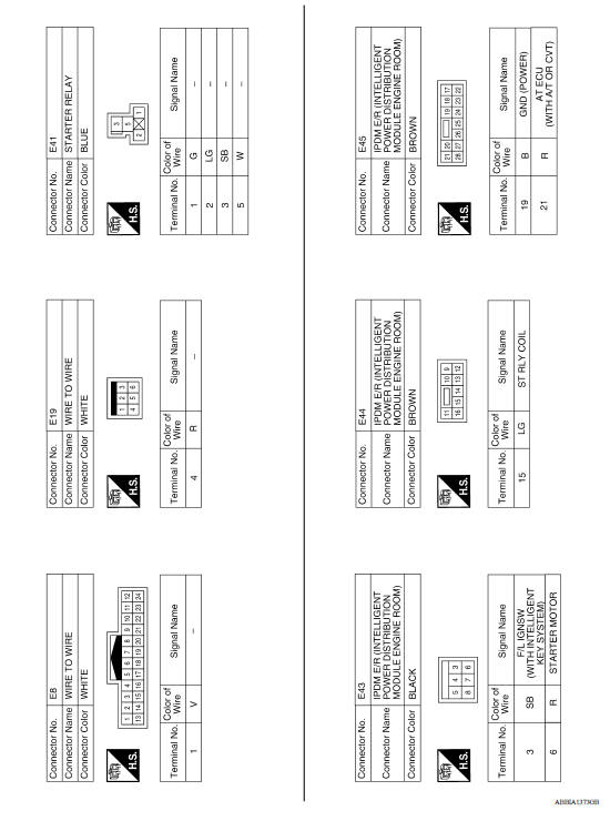
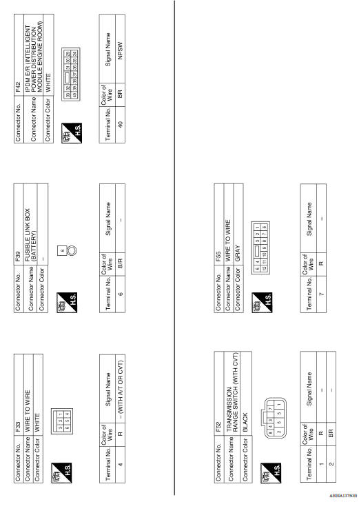
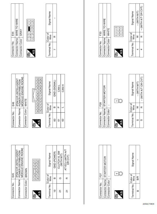
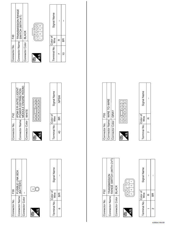
Wiring Diagram - Without Intelligent Key System
 Exhaust system
Exploded View 1. Heated oxygen sensor 2 2. Catalyst cover (upper) 3. Seal bearing 4. Catalyst cover (lower) 5. Spring 6. Spring 7. Mounting rubber 8. Main muffler 9. Ring gasket 10. Center mu ...

Other materials:
Meters and gauges
Type A (if so equipped)
1. Tachometer
2. Speedometer
3. Fuel gauge
4. Odometer
Twin trip odometer
Trip computer
5. Continuously Variable Transmission
(CVT) position indicator (if so equipped)
Automatic Transmission (A/T) position
indicator (if so equipped)
6. Instrument brightness con ...
Towing your vehicle
When towing your vehicle, all State (Provincial in
Canada) and local regulations for towing must be
followed. Incorrect towing equipment could damage
your vehicle. Towing instructions are available
from a NISSAN dealer. Local service operators
are generally familiar with the applicable laws
an ...
Categories
- Manuals Home
- Nissan Versa Owners Manual
- Nissan Versa Service Manual
- Video Guides
- Questions & Answers
- External Resources
- Latest Updates
- Most Popular
- Sitemap
- Search the site
- Privacy Policy
- Contact Us

0.0052