Nissan Versa (N17): Exhaust system
Exploded View
1. Heated oxygen sensor 2 2. Catalyst cover (upper) 3. Seal bearing 4. Catalyst cover (lower) 5. Spring 6. Spring 7. Mounting rubber 8. Main muffler 9. Ring gasket 10. Center muffler 11. Mounting rubber 12. Seal bearing 13. Exhaust front tube
Removal and Installation
WARNING:
- Perform the operation with the exhaust system fully cooled. The system will be hot just after engine stops.
- Be careful not to cut your hand on the heat insulator edge.
CAUTION: Be sure to use genuine exhaust system parts or equivalents because they are designed for heat resistance, corrosion resistance, proper fit, and shape
REMOVAL
Remove the exhaust system components using power tools.
- Disconnect each joint and mounting as necessary.
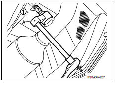
- Remove heated oxygen sensor 2 (1) as needed using Tool (A).
Tool number : KV10114400 (J-38365)
CAUTION: Be careful not to damage heated oxygen sensor.
INSTALLATION
Installation is in the reverse order of removal.
CAUTION:
- Always replace seal bearings and ring gaskets with new ones when reassembling.
- Temporarily tighten nuts and bolts. Check each part for unusual interference and mounting rubber interference, and then tighten them to the specified torque.
- Discard any heated oxygen sensor which has been dropped from a height of more than 0.5 m (19.7 in) onto a hard surface such as a concrete floor; replace with a new one.
- Before installing a new heated oxygen sensor 2, clean exhaust system threads using the heated oxygen sensor thread cleaner and apply anti-seize lubricant.
Oxygen sensor thread cleaner : - (J-43897-18)
Oxygen sensor thread cleaner : - (J-43897-12)
- Do not over-tighten heated oxygen sensor 2. Doing so may cause damage to the heated oxygen sensor 2, resulting in the MIL coming on.
- Prevent rust preventives from adhering to the sensor body.
- If heat insulator is badly deformed, repair or replace it. If deposits such as mud pile up on the heat insulator, clean and inspect them.
- When installing heat insulator avoid large gaps or interference between heat insulator and each exhaust pipe.
- Remove deposits from the sealing surface of each connection. Connect them securely to avoid exhaust leaks.
- Avoid twisting or deforming the mounting rubbers when installing them.
Exhaust Manifold to Exhaust Front Tube
- When installing the seal bearing (2), insert it into the exhaust manifold (1) in the direction shown.
- When installing the spring (3) and bolt (4), ensure the following:
- Make sure the spring (3) sits properly on the flange surface by aligning it to the locator dimples (A).
- Make sure the bolt (4) does not contact the inside of the flange bolt hole.
(5) : Exhaust front tube
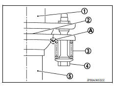
CAUTION: Be careful not to damage seal bearing surface when installing.
- Tighten bolt with spring.
CAUTION:
- Ensure springs are seated correctly on the flange and not sitting on (A).
- Assemble the seal bearing so that the bolt is located in the center of the flare flange hole without contact with the flange.
Exhaust Front Tube to Center Muffler
- When installing the seal bearing (2), insert it into the exhaust manifold (1) in the direction shown.
- When installing the spring (3) and bolt (4), ensure the following:
- Make sure the spring (3) sits properly on the flange surface by aligning it to the locator dimples (A).
- Make sure the bolt (4) does not contact the inside of the flange bolt hole.
(5) : Exhaust front tube
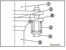
CAUTION: Be careful not to damage seal bearing surface when installing.
- Tighten bolt with spring.
CAUTION:
- Ensure springs are seated correctly on the flange and not sitting on (A).
- Assemble the seal bearing so that the bolt is located in the center of the flare flange hole without contact with the flange.
INSPECTION AFTER INSTALLATION
- Ensure the clearance between the tail tube and rear bumper is evenly spaced.
- Check exhaust tube joints for exhaust leaks and unusual noises with the engine running.
- Ensure the mounting brackets and mounting rubbers are installed properly and free from undue stress.
- Improper installation could result in excessive noise and vibration.
 Precautions
Precaution for Supplemental Restraint System (SRS) "AIR BAG" and "SEAT BELT PRE-TENSIONER" The Supplemental Restraint System such as "AIR BAG" and "SEAT BELT PRE-TENSIONER", us ...
Precautions
Precaution for Supplemental Restraint System (SRS) "AIR BAG" and "SEAT BELT PRE-TENSIONER" The Supplemental Restraint System such as "AIR BAG" and "SEAT BELT PRE-TENSIONER", us ...
Other materials:
Air breather hose
Exploded View
1. Cap 2. Air breather hose 3. 2-way connector
Removal and Installation
REMOVAL
Remove air cleaner case. Refer to EM, "Removal and Installation".
Remove air breather hose from the 2-way connector.
CAUTION:
When removing air breather hose, be sure to hold 2- ...
P2857 Clutch A pressure
DTC Logic
DTC DETECTION LOGIC
DTC
Trouble diagnosis name
DTC detection condition
Possible causes
P2857
Clutch A pressure engagement
performance
The auxiliary gearbox gear ratio is 2.232 or
more for the auxiliary gearbox 1GR ratio continuously
for 5 seconds o ...
Categories
- Manuals Home
- Nissan Versa Owners Manual
- Nissan Versa Service Manual
- Video Guides
- Questions & Answers
- External Resources
- Latest Updates
- Most Popular
- Sitemap
- Search the site
- Privacy Policy
- Contact Us

0.0053