Nissan Versa (N17): Rear window defogger relay
Description
Power is supplied to the rear window defogger with BCM control.
Component Function Check
1.CHECK FUNCTION
1. Turn ignition switch ON.
2. Check that an operation noise of rear window defogger relay can be heard when turning the rear window defogger switch ON.
Is the inspection result normal?
YES >> Rear window defogger relay function is OK.
NO >> Refer to DEF "Diagnosis Procedure"
Diagnosis Procedure
Regarding Wiring Diagram information, refer to DEF "Wiring Diagram".
1.CHECK REAR WINDOW DEFOGGER RELAY POWER SUPPLY CIRCUIT
1. Turn ignition switch OFF and disconnect rear window defogger relay connector.
2. Turn ignition switch ON.
3. Check voltage between rear window defogger relay harness connector and
ground.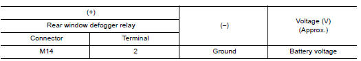
Is the inspection result normal?
YES >> GO TO 3.
NO >> GO TO 2.
2.CHECK FUSE
1. Turn ignition switch OFF.
2. Check 10A fuse (No. 5).
Is the inspection result normal?
YES >> Check ignition power supply circuit. Refer to PG "Wiring Diagram - Ignition Power Supply -".
NO >> If fuse is blown, be sure to eliminate cause of malfunction before installing new fuse.
3.CHECK REAR WINDOW DEFOGGER RELAY CONTROL CIRCUIT
1. Turn ignition switch OFF.
2. Disconnect BCM connector.
3. Check continuity between BCM harness connector and rear window defogger
relay harness connector.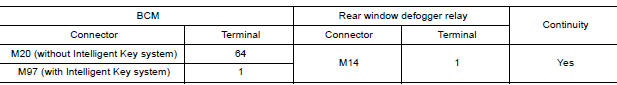
4. Check continuity between BCM harness connector and ground.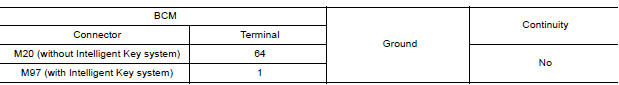
Is the inspection result normal?
YES >> GO TO 4.
NO >> Repair or replace harness.
4.CHECK REAR WINDOW DEFOGGER RELAY
Refer to DEF "Component Inspection".
Is the inspection result normal?
YES >> Replace BCM. Refer to BCS "Removal and Installation" (with Intelligent Key) or BCS "Removal and Installation" (without Intelligent Key).
NO >> Replace rear window defogger relay.
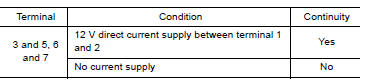
Component Inspection
Check continuity between terminal 3 and 5, 6 and 7.
 Rear window defogger switch
Description The rear window defogger is operated by pressing the rear window defogger switch ON. The indicator lamp in the rear window defogger switch illuminates while the rear window d ...
Rear window defogger power supply
and ground circuit
Description Heats the heating wire with the power supply from the rear window defogger relay to prevent the rear window from fogging up. ...
Other materials:
Exterior front
1. Engine hood
2. Windshield
3. Wiper and washer switch
4. Power windows (if so equipped)
5. Door locks. NISSAN Intelligent Key
(if so equipped). Key fob (if so equipped). Keys
6. Mirrors
7. Tire pressure. Flat tire. Tire chains
8. Headlight and turn signal switch. Replacing bulbs
9. Fo ...
Recommended fluids/lubricants and capacities
The following are approximate capacities. The actual refill capacities may
be a little different. When refilling, follow the procedure
described in the "Do-it-yourself" section to determine the proper refill
capacity.
...
Categories
- Manuals Home
- Nissan Versa Owners Manual
- Nissan Versa Service Manual
- Video Guides
- Questions & Answers
- External Resources
- Latest Updates
- Most Popular
- Sitemap
- Search the site
- Privacy Policy
- Contact Us

0.0053